Lobaro USB Config Adapter
The Lobaro USB configuration adapters connects the configuration serial uart of our devices to a PC. It is used for:
- Sensor initial configuration, e.g. network parameters like LTE APN point
- Viewing firmware log/debug diagnostic output
- Firmware updates
- Using our free Lobaro Maintenance Tool PC software (If in doubt, always use the most recent version to ensure optimal compatibility with older hardware).
Current adapter versions do not provide power supply to the connected device by default.
The connected device must therefore be powered externally during operation.
There is a bridge on the PCB to enable power supply, but it is not populated by default.
There is no "V3" configuration adapter.
The naming was intentionally changed from V2 to V4 to align with the V4 product family.
- "V4" corresponds to the current adapter generation
- Product naming may differ from internal hardware revisions
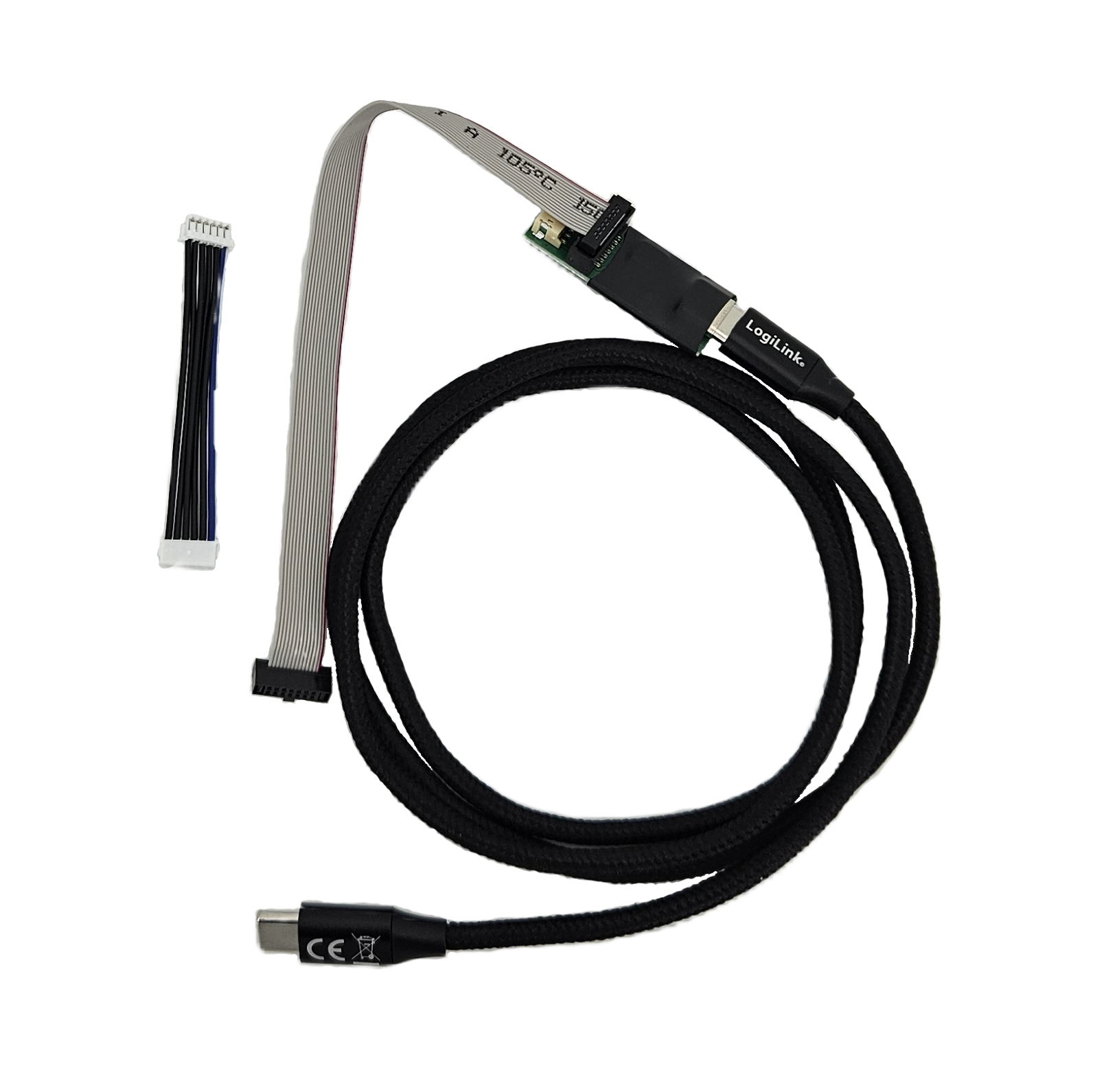
USB Adapter V4
Installation
The FT231 USB-to-UART chip which is used for this Adapter is natively supported by most modern operating systems (Windows, Linux, macOS).
In most cases, no manual driver installation is required.
If the adapter is not recognized automatically, drivers can be downloaded from the official FTDI website:
Features
- PC USB-C connection
- 6 pin config cable port
- 14 pin config cable port
- 3D-printed enclosure
Compatibility
- Gateway series
- V4 series
- V3 series
- Other devices
- All Lobaro devices with 6-pin or 14-pin configuration ports
On the hardware side, nothing was changed specifically to restrict compatibility with older devices.
However, V4.x adapters (V4.1 / V4.2) use a different USB-to-UART chip.
With older software versions, the new config adapter may therefore be incompatible with all devices.
To ensure compatibility, always use the latest version of the Lobaro Config Tool, which automatically detects and supports the new chip.
Physical Connection
Connect your Lobaro Device to the USB-port of your computer using the Lobaro Config Adapter (USB-C).
- If you are using a Lobaro device with a 14-Pin socket, plug 14-pin Ribbon Cable into the single socket on the lobaro device.
- If you are using a Lobaro device with a 6-pin socket, the 6-pin 6 PIN JST ZH connector may be used to connect with discontinued devices, see here.
The config adapter does not power the connected device by default.
Make sure the target device is powered externally.
USB Adapter V2
Installation
The CP2102 uart serial USB driver must be installed, it can be downloaded at the Silicon Labs Homepage.
- CP210x_Universal_Windows_Driver.zip for Windows 11+
- CP210x Windows Drivers v6.7.6 for Windows 10 and earlier
Features
- PC USB-C connection
- 6 pin config cable port
- 12 pin config cable port
Compatibility
- Gateway V4 series
- Gateway V3 series
- All Lobaro products with 6 pin configuration port.
- All Lobaro products with 14 pin configuration port.
Order-Code
1200342
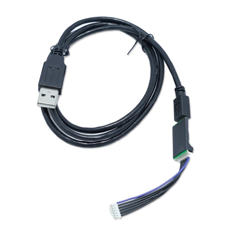
USB Adapter V1
Installation
The CP2102 uart serial USB driver must be installed, it can be downloaded at the Silicon Labs Homepage.
- CP210x_Universal_Windows_Driver.zip for Windows 11+
- CP210x Windows Drivers v6.7.6 for Windows 10 and earlier
Features
- PC Micro-USB connection
- 6 pin config cable port
Compatibility
- Gateway V3 series
- Hybrid Gateway series
- All Lobaro products with 6 pin configuration port.
The original adapter in version 1 was used with the 6 pin configuration port on the Lobaro GW.
The configuration adapter, including a 1m USB cable, has been discontinued and functionally replaced by version 2
Physical connection
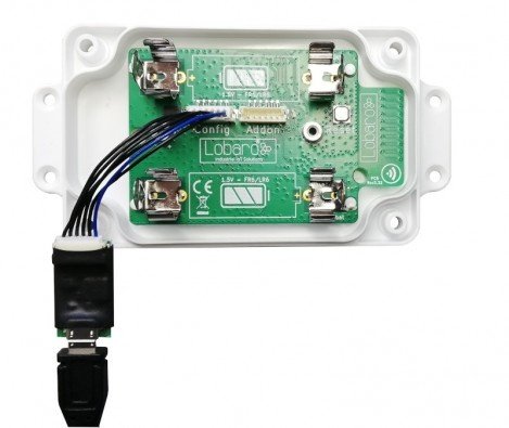
Connect your Lobaro Device to the USB-port of your computer using the Lobaro Config Adapter. The 6-pin connector must be plugged into the white rectangular socket on the device that is labeled with the word CONFIG. The location of the socket is dependent on the specific device and hardware version you are trying to attach. See the hardware specific product description for the individual connector location.
Some devices can be powered by the 3.3V the config adapter can provide out of the USB Port. Other devices, mostly the NB-IoT/LTE-M enabled cellular IoT boards or the need their normal power supply connected as well. If in doubt, just make sure you have the device powered!
Schematic
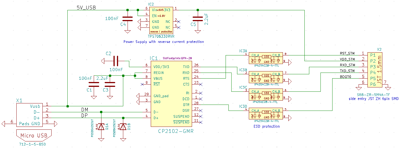
Connector Type
The USB adapter uses a six-wire JST-ZH series connector for attaching to Lobaro hardware at the config connector.
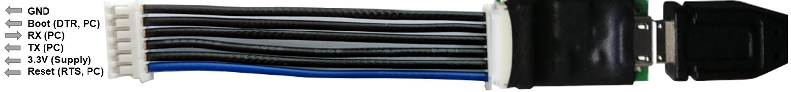
Control Lines
- Boot0 of Lobaro sensors is connected to DTR line of the PC uart
- Reset (active low) of Lobaro sensors is connected to RTS line of the PC uart
Normally the handling of these uart control lines is done automatically by the Lobaro PC tool. When using an alternative uart terminal tool make sure you setup the RTS and DTR lines correctly or simply cut the DTR/RTS wires from the USB adapter if the reset and/or bootloader control lines are not needed and you simply want to look at the devices log output.
DTR control line
- Low / true => Run Firmware after Reset (Default since BOOT0 has internal pull-down)
- High / false => Run Bootloader after Reset
RTS control line
- High / false => Run Firmware / Bootloader (Default since RESET has internal pull-up)
- Low / true => Chip in RESET mode (not running)