Wireless M-Bus Gateway V4 with 4-20 mA Add-On
Description
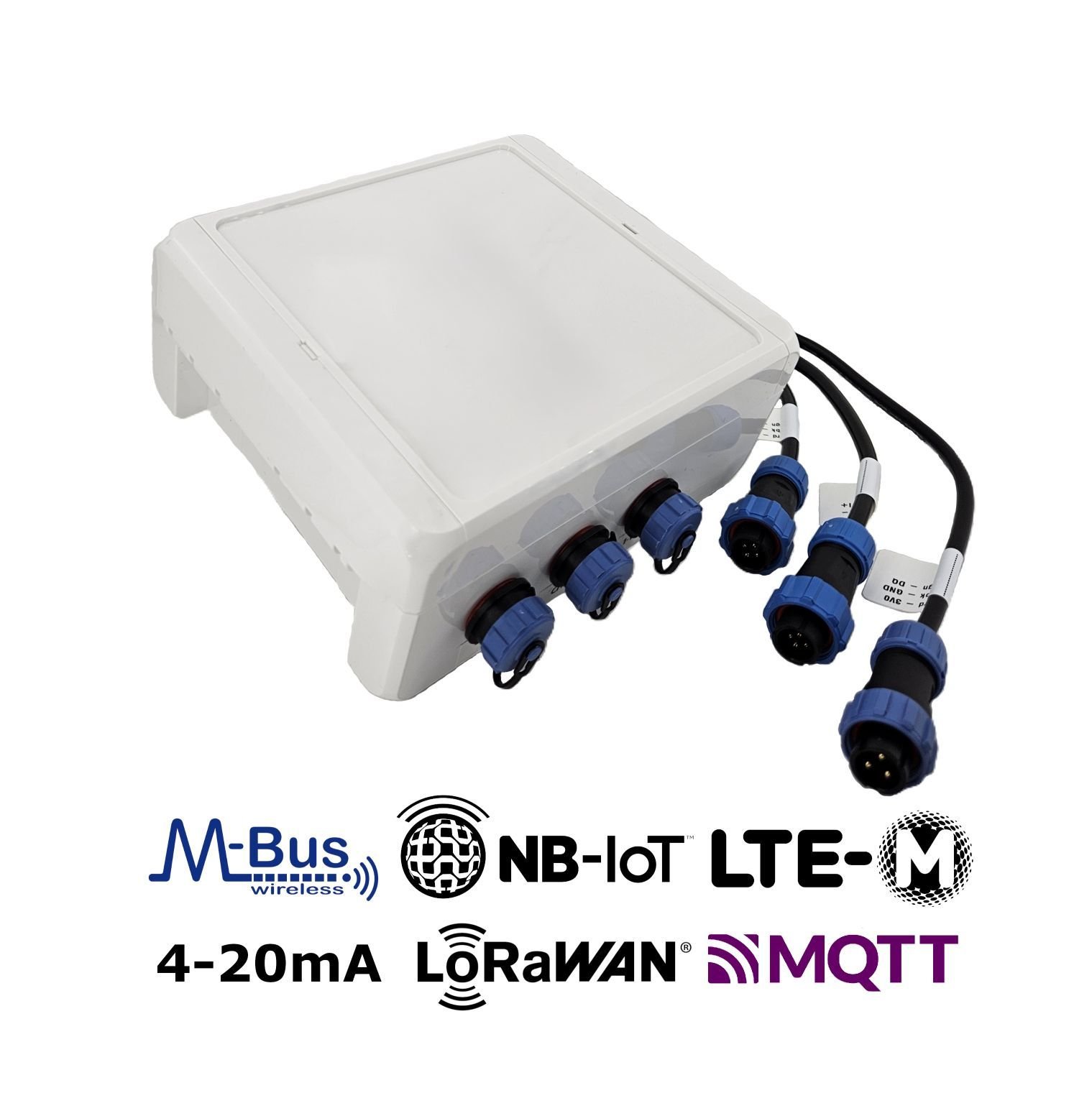
Gateway for remote reading of wireless M-Bus meters and external sensors (4–20 mA and 1-Wire temperature sensors) via NB-IoT, LTE-M mobile radio or LoRaWAN to the Internet. Suitable for indoor and weather-protected outdoor installation.
In addition to all the features of the Wireless M-Bus Gateway V4, this variant provides:
-
2 analogue 4–20 mA input channels for industrial sensors. Each channel is supplied with an extra 12V (1W) supply voltage for sensor supply. Connection with each 4-pin channel (I+, I-, 12V, GND) can be established over a 22 cm cable connection.
-
A 1-Wire interface for up to 20 temperature sensors (DS18B20). Connection with each 3-pin channel (3V, GND, DQ) can be established over a 22 cm cable connection.
Product Components
This product is manufactured by Lobaro using the components listed below. Detailed information about the firmware and other components can be found in their respective descriptions.
Please use the links provided to access comprehensive product details.
| Component | Manual / Description | Additional note |
|---|---|---|
| Firmware | app-nrf91-origin | See here for available firmware updates |
| Housing (Standard) | LoCube | 122 mm (l) × 82 mm (w) × 55 mm (h) |
| Housing (Compact) | Compact Lobaro Box Housing | 114.30 mm (w) × 59.30 mm (l) × 26.80 mm (h) |
Power Supply | Battery | (Li-SOCl2) 3.6 V, 38 Ah |
| External power supply (12 V or 230 V) | Please contact | |
Optional Accessories | External Antenna (SMA) instead of | Please contact |
IP68 encapsulation with transparent, | ||
| LoCube Backplate Wall Mounting Kit | ||
| Pole Mounting Kit |
Firmware Updates
The latest firmware can be found here:
-
For further information on how to update the device, refer to: Firmware Update.
A remote firmware update over LoRaWAN is currently not possible.
Product Identification
- Name: Gateway V4 + 4-20 mA
- Type: LOB-GW4-420-1W
- MPN / Ordering code: 1200588
Datasheet & Quickstart
Please contact our sales team.
Product specific details
LED signal patterns
The device has 3 three LEDs (B, G, R = Blue, Green, Red), labeled Status on the PCB: 🔵🟢🔴.
Patterns during booting/restart
- 🔵⚪🔴 B and R on: Device is in Bootloader Mode (not actively running, remove config adapter press reset to leave Bootloader Mode).
- 🔵->🟢->🔴 Quick cycle B, G, R for ~0.5s: Device just booted, either after power on, reset by button or software, or after a hard failure.
- ⚪⚪🔴 R flashes repeatedly on and off in 1s interval: critical failure during boot (failed to start application).
- 🔵🟢⚪ B and G on: Remote Firmware Update.
Patterns during normal operation
- 🔵⚪⚪ B flashes 1s on and 1s off in loop: building LTE connection to mobile provider. Followed by:
- ⚪🟢⚪ Short G flash on success.
- ⚪⚪🔴 Short R flash after connection failed.
- ⚪🟢⚪ G flash during installation mode while collecting wireless M-Bus telegrams.
Exceptional patterns
- 🔵⚪🔴/🔵🟢⚪ Quickly changing between R & B and G & B every 5s in a loop: Modem is in connection restriction mode - keep device on power, will fix itself after 30min.
Configuration
The device is shipped with default configuration parameters. The configuration can be changed via the 6-pin config port using the Lobaro USB Configuration Adapter. More information about the usage of the configuration tools can be found in our documentation.
Remote Configuration is also supported after initial network connection.
Default Values are the firmware defaults. Depending on the application the device may be delivered with different settings.
General Parameters
| Description | Key | Type | Possible Values | Default |
|---|---|---|---|---|
| Uplink channel selection | WAN | String | lte or lorawan | lte |
| Listen Cron [UTC+0] | listenCron | String | Any CRON String | 0 0 12 * * * |
| Days without connectivity until device reset | LostReboot | Number | Any, e.g., 5 | 3 |
Detailed Description
WAN Parameter
LPWAN technology is used for connection and data communication with the backend server. This can be either cellular LTE (NB-IoT, LTE-M) or LoRaWAN.

lte: Utilizes cellular technologies, either NB-IoT or LTE-M.lorawan: Employs LoRaWAN with OTAA (Over-The-Air Activation).
- LoRaWAN uplinks and downlinks are limited to 52–222 bytes, depending on the DataRate (connection quality):
- Uplinks containing longer wMBUS telegrams are split across multiple LoRaWAN messages.
- Uplinks with numerous wMBUS telegrams may take significant time due to LoRaWAN's duty-cycle limitations.
- Downlinks with large configuration values (e.g., long whitelists) must be split into multiple messages, which can be challenging to implement.
- Limited metadata:
- Status telegrams include less information due to reduced uplink channel capacity.
- No remote firmware update capabilities.
listenCron Parameter
The listen cron specifies when the device wakes up to receive data via enabled wireless M-Bus and other radio protocols. Each listening period is followed by data upload using the configured WAN technology. The ideal interval largely depends on the device's power supply (battery-powered vs. externally powered) and the application's need for new metering data. Typical intervals range from every 15 minutes to 14 days between consecutive readouts.
Learn more about CRON configuration parameters.
Wireless M-Bus Meter Reading
| Description | Key | Type | Possible Values | Default |
|---|---|---|---|---|
| WMBUS C1/T1 Listen Duration [s] | cmodeDurSec | Number | Number of seconds0 = Do not collect C1/T1Max Value= 36000 | 300 |
| WMBUS S1 Listen Duration [s] | smodeDurSec | Number | Number of seconds0 = Do not collect S1Max Value= 36000 | 0 |
| Sensus RF Listen Duration [s] | xmodeDurSec | Number | Number of seconds0 = Do not collect X-ModeMax Value= 36000 | 0 |
| Müller-Funk Listen Duration [s] | umodeDurSec | Number | Number of seconds0 = Do not collect U-ModeMax Value= 36000 | 0 |
| WMBUS ID Filter List | devFilter | String | List, e.g.88009035,13456035 | [not set] |
| WMBUS Type Filter List | typFilter | String | List, e.g.08,07 | [not set] |
| WMBUS M-Field Filter List | mFilter | String | List, e.g.DME,ITW,SEN,QDS | [not set] |
| WMBUS CI-Field Filter List | ciFilter | String | List, e.g.8a,72 | [not set] |
| WMBUS Telegram Upload Limit | maxTelegrams | Number | Any number of max. Telegrams0 = no limit. | 0 |
Detailed Description
*modeDurSec Parameters
Parameters: cmodeDurSec smodeDurSec xmodeDurSec umodeDurSec
The duration, specified in seconds (e.g., 300 for 5 minutes), defines how long the device collects metering data for
each corresponding wireless protocol. Each listening period is executed sequentially based on the configured durations.
Once all listening periods are complete, the collected meter telegrams are transmitted using the configured WAN
technology.
The maximum duration that can be specified is 10 hours, i.e. 36,000 seconds. Please note that such long listening periods will drain the battery very quickly. If in doubt, please consult Lobaro.
*Filter Parameters
Parameters: devFilter ciFilter mFilter typFilter
Filters are applied to meters based on wireless M-Bus-related fields to determine which telegrams are collected and uploaded. These filters include:
mFilter: Manufacturer filter – filters telegrams by the 3-letter manufacturer code included in every telegram ( e.g.,LOBfor Lobaro GmbH).typFilter: Device Type filter – filters telegrams by the 2-hex-digit code that defines the type of sending device (e.g.,07for water meters).devFilter: Device filter – filters telegrams by the 8-digit ID that is mandatory for each sending device (e.g.,87654321).ciFilter: CI-Field filter – filters telegrams by the 2-hex-digit CI-Field included in every telegram. This field is a technical code that describes the purpose of the telegram (e.g.,8a).
These filters help refine data collection to target specific devices or device types.
For a detailed explanation, read more about telegram filter parameterization.
Blacklist
Each filter parameter can be preceded with an exclamation mark (!) to convert the whitelist into a blacklist.
This applies to the entire filter parameter, not to individual entries within the list. For example:
mFilter=LOBwill collect only telegrams from Lobaro GmbH (whitelist).mFilter=!LOBwill exclude telegrams from Lobaro GmbH (blacklist).
maxTelegrams Parameter
Set a hard limit on the number of telegrams to be collected and uploaded. The firmware will stop collecting once this limit is reached, regardless of the elapsed time. This can help conserve battery life and data volume, especially if the device is located in an area with a high density of meters.
When filtering for a single telegram, the parameter can be set to 1, causing the device to stop listening immediately
after the desired telegram is received.
LTE Connection
| Description | Key | Type | Possible Values | Default |
|---|---|---|---|---|
| LTE Lobaro Platform Host | Host | IP / URL | List of various Endpoints | coaps://platform.lobaro.com |
| LTE MCC+MNC Code | Operator | Number | e.g. 26201 (Dt. Telekom) | [not set] |
| LTE Band | Band | Number | 3 or 8,20 or 3,8,20 | 3,8,20 |
| LTE APN | APN | String | any APN | * |
| LTE SIM Pin | PIN | Number | 4 digits pin, e.g. 1234 | [not set] |
| LTE NB-IoT on/off | UseNbiot | Bool | true or false | true |
| LTE M1 on/off | UseLtem | Bool | true or false | true |
| LTE DNS Servers used | DNS | IP | List of DNS server IPs | 9.9.9.9,1.1.1.1 |
| Plain UDP Host | UdpHost | IP | any, e.g 94.130.20.37 | [not set] |
| Plain UDP Port | UdpPort | Number | any, e.g 3333 | [not set] |
Detailed Description
Host Parameter
- Lobaro Platform CoAP
- MQTT
Hostname or IP of the Lobaro Platform instance CoAP endpoint to which the gateway communicates using UDP.
- Using DTLS:
coaps://platform.lobaro.com - No DTLS:
coap://platform.lobaro.com - Plain IP:
94.130.20.37(platform.lobaro.com)
It's also possible to configure a list of URLs to implement a fallback mechanism. This is particulary helpful
for
combining DTLS and non DTLS connection attempts: coaps://platform.lobaro.com,coap://platform.lobaro.com
The device can communicate directly via MQTT. See MQTT → Host Parameter.
LTE Parameters
Parameters: APN Operator Band, PIN
Basic parameters are required to configure the NB-IoT or LTE-M connection. These settings must align with the SIM card
and network provider used. Typically, the default parameters work well, as they enable the modem to automatically select
and join the network using SIM card information. However, if the APN (Access Point Name) is known, it is recommended
to configure it for optimal performance.
Read more about LTE network configuration parameters.
UseNbiot UseLtem
The modem supports both NB-IoT and LTE-M technologies. By default, both are enabled, allowing the cellular modem to
automatically select the most suitable network type based on the location. However, you can force the modem to use a
specific technology by setting one parameter to false, ensuring the other remains enabled (set to true). At least
one technology must always be active.
UdpHost UdpPort
This feature is deprecated and not recommended for production use. Lobaro provides limited support for errors caused by using raw UDP upload.
Instead of sending metering data to the Lobaro IoT Platform, the data can alternatively be sent to an external UDP socket. This option is useful if you prefer to keep metering data off external servers while still using the Lobaro Platform to control your gateways.
UdpHost: IP address to upload plain telegrams via UDP.[not set]: Defaults to uploading data to the Lobaro IoT Platform using the configured Host parameter.UdpPort: Port number to upload plain telegrams via UDP.- Only used if
UdpHostis set.
Even when metering data is sent to an external server, the firmware typically still requires a connection to a Lobaro Platform instance to send status information, perform remote configurations, or handle firmware updates.
For solutions that allow all communication without the Lobaro Platform, such as direct MQTT to an external broker, contact Lobaro for potential options.
LoRaWAN Connection
| Description | Key | Type | Possible Values | Default |
|---|---|---|---|---|
| DevEUI | DevEUI | byte[8] | any | Device EUI64 |
| AppEUI / JoinEUI (1.1) | AppEUI/JoinEUI | byte[8] | any | random |
| AppKey | AppKey | byte[16] | any | random |
| NwkKey (1.1) | NwkKey | byte[16] | any | 00000000000000000000000000000000 |
| Days between Timesync | TimeSync | Number | any | 3 |
| Payload Format | PayloadFormat | Number | 0, 1, 2 | 0 |
| Use OTAA | OTAA | Bool | true or false | true |
| Random TX Delay [s] | RndDelay | Number | any | 10 |
| Spreading Factor | SF | Number | 7-12 | 12 |
| Transmission Power | TxPower | Number | 2-14 | 14 |
| Adaptiv Data Rate | ADR | Bool | true or false | true |
| LoRaWAN max. Payload Length | loraPLMax | Number | 10 to 241 | 100 |
Detailed Description
LoRaWAN 1.1 is experimental and not certified. For production environments, we recommend using LoRaWAN 1.0.2.
Depending on configuration some parameters are not available.
NwkKey Parameter
The Network Key (NwkKey) is used for LoRaWAN 1.1. If set to zeros (00000000000000000000000000000000) or to the same value as the AppKey, the device will stick to LoRaWAN 1.0.2 which is the recommended mode of operation.
PayloadFormat Parameter
Used encoding of the wmBus LoRaWAN uplink payload packets.
0= Encoding in ports with static message length1= prefix bytes and time2= prefix bytes, time, and rssi
For a detailed specification of the payload formats, please refer to the LoRaWAN Communication page.
Special
| Description | Key | Type | Possible Values | Default |
|---|---|---|---|---|
| Verbose UART Log | verbose | Bool | true or false | false |
| Addon RAM configuration | extRam | String | Lobaro Internal | [not set] |
| Live Mode | liveMode | String | [not set] | |
| Operation Mode | opMode | Number | Lobaro Internal | 1 |
Detailed Description
liveMode Parameter
An empty string disables the live mode.
suppression=<seconds> enable live mode with suppression of duplicate telegrams for seconds
Analog Channel Parameters
| Description | Key | Type | Possible Values | Default |
|---|---|---|---|---|
| Enable measurement on 4–20 mA input channel 1 (CH1) | ch1Enable | Bool | true / false false = channel disabled | true |
| Number of seconds to wait for the CH1 sensor to get ready after power on | ch1PreReadSec | Number | Seconds (integer) 0… | 1 |
| Number samples to take for a single CH1 measurement | ch1Samples | Number | 1-1000 | 200 |
| Scaling factor applied to the raw CH1 value | ch1Factor | Number | Numeric (float) e.g. 1.0, 0.1 | 1 |
| Offset added to the CH1 value after scaling | ch1Offset | Number | Numeric (float) e.g. 0, -5.0 | 0 |
| High alarm threshold for CH1 measurement value | ch1AlarmHigh | Number | Numeric (float) empty = disabled | [not set] |
| Low alarm threshold for CH1 measurement value | ch1AlarmLow | Number | Numeric (float) empty = disabled | [not set] |
| Enable measurement on 4–20 mA input channel 2 (CH2) | ch2Enable | Bool | true / false false = channel disabled | true |
| Number of seconds to wait for the CH2 sensor to get ready after power-on | ch2PreReadSec | Number | Seconds (integer) 0… | 1 |
| Number of samples taken for a single CH2 measurement | ch2Samples | Number | 1-1000 | 200 |
| Scaling factor applied to the raw CH2 value | ch2Factor | Number | Numeric (float) | 1 |
| Offset added to the CH2 value after scaling | ch2Offset | Number | Numeric (float) | 0 |
| High alarm threshold for CH2 measurement value | ch2AlarmHigh | Number | Numeric (float) empty = disabled | [not set] |
| Low alarm threshold for CH2 measurement value | ch2AlarmLow | Number | Numeric (float) empty = disabled | [not set] |
| Cron schedule used while an alarm is active, overriding the normal device cron | alarmCron | String | Cron expression (string) empty = no override | [not set] |
| Number of seconds CH1 stays powered after first power-on or brownout | ch1PwrAfterBrownoutDur | Integer | Seconds (integer) 0 = disabled | 0 |
Detailed Description
chXFactor and chXOffset Parameters
The measured raw value is multiplied by chXFactor and then chXOffset is added. All further calculations and alarm checks are done with this derived value.
chXAlarmLow and chXAlarmHigh Parameters
If the calculated measurement value is above chXAlarmHigh or below chXAlarmLow, an alarm is triggered. The number of triggered alarms and the time in the alarm state is measured and transmitted.
alarmCron Parameter
In case of an active alarm, this cron is used instead of the regular cron. If empty, the regular sensor cron will be used.
OneWire Multi-Temperature Sensor Reading
| Description | Key | Type | Possible Values | Default |
|---|---|---|---|---|
| Number of readouts to be uploaded together (saves energy) | MTempAcc | Number | 1-600 | 1 |
List of sensor IDs or * for scanning | MTempIDs | String | * | |
| Include Sensor ID in upload (LoRaWAN) | MTempSendID | Bool | true or false | false |
Detailed Description
MTempAcc Parameter
The MTempAcc parameter specifies the number of readouts before the data is uploaded. When set to 1 the data is uploaded immediately.
The data may be uploaded earlier if not enough free memory is available to store the measurements.
MTempIDs Parameter
The MTempIDs parameter specifies a list of sensor IDs separated by a ,. If the string it empty, all sensor readings are disabled. If a * is specified, a scan will be executed at boot and all new sensors added to the list.
A complete sensor ID consists of 8 bytes:
byte    0: family code
bytes 1-6: serial number
byte    7: crc cecksum
In data transmittions only the serial number is used by the device, family code and checksum are omitted for uploads. In configurations the full ID is used.
MTempSendID Parameter
If MTempSendID is set to true, the Sensor-ID is included in LoRaWAN transmissions. If set to false only the temperature values are transmitted.
Upload Formats LoRaWAN
Communication with this gateway version via LoRaWAN is currently not possible.
Upload Formats LTE
CoAP Protocol
The protocol details of the CoAP implementation are not publicly disclosed and are intended for use exclusively with the Lobaro IoT Platform. For integration with third-party systems, MQTT is the preferred protocol.
If you require access to this and MQTT is not an option, please contact Lobaro directly.
MQTT Protocol
MQTT Downlink Payload Size Limit
The maximum supported MQTT downlink payload size is approximately 4096 bytes (4 KiB). This includes the complete MQTT message payload (e.g. JSON configuration objects). Messages exceeding this size may result in configuration rejection.
Note: The effective usable payload size may be slightly lower due to protocol overhead.
Practical Implication
Large configuration objects (e.g. long device whitelists) must remain below this limit. Example: A comma-separated list of ~440 device IDs typically reaches the upper boundary.
Example JS Parser
A production-ready parser (including split telegram reassembly where applicable, AES-128 decryption for encrypted wM-Bus telegrams, and OMS-compliant data interpretation) is implemented within the Lobaro Platform.
Customers using the Lobaro Platform can utilize this parser directly as part of the platform processing pipeline.
If you are operating a Lobaro Gateway without using the Lobaro Platform, we can provide restricted platform access upon request. This allows you to inspect the parser behavior and use it as a technical reference for your own backend implementation.
Please contact our support team if you require access or further integration details.
Declaration of Conformity
| Download CE declaration of conformity |