Modbus
Modbus defines four different object types form which values can be read: Coils, Discrete Inputs, Input Registers, and Holding Registers. Of those four, Coils and Holding Registers can also be written to. Coils and Discrete Inputs hold single bit values while Input Registers and Holding Registers hold 16 bit values. For values that cannot fit into 16 bit, it is customary to use multiple consecutive registers to hold the value. Modbus does not define what the bytes in the registers represent; it is up to the creator of the Modbus Slave Device to specify how to interpret the stored bits. A 16 bit register could be used to hold a single byte value, for example, or four consecutive registers could hold a double precision floating point number. Storing texts as ASCII characters is also possible. For integer numbers in particular it there is no defined byte order, nor signage definition. Because of those ambiguities it is not possible for the Lobaro LoRaWAN Bridge to understand the data read from/written to Slave Devices. All communications therefore simply forward raw Modbus Commands and Responses with their payload, as it communicated on the Bus. Any check sums (CRC16 for RTU, LRC for ASCII) are excluded from LoRaWAN communications or the Bridge's configuration, as there are other check sums in work their already.
For a deeper introduction into Modbus please refer to https://en.wikipedia.org/wiki/Modbus.
Online Tools
Examples of Modbus commands:
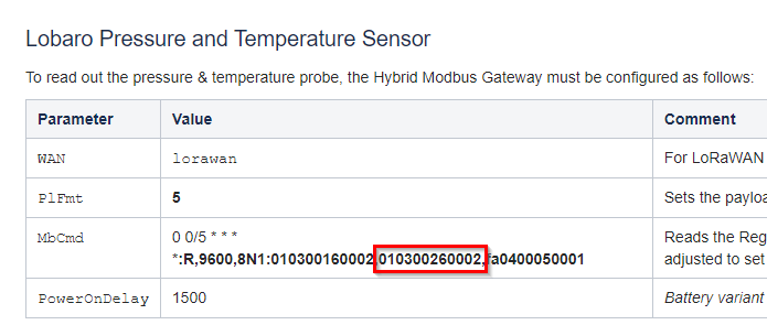
MbCmd | 0 0/5 * * * ***:**R,9600,8N1:010300160002,010300260002,fa0400050001 |
|---|
- 0 0/5 * * * Cron (every 5 minutes)
- R,9600,8N1 communication parameters (9600 baud, 8 data bits, no parity)
Modbus Command:
010300260002
01 Slave Address
03 Function (Read Holding Register)
00 Starting Address Hi
26 Starting Address Lo (Decimal 38)
00 Quantity of Registers Hi
02 Quantity of Registers Lo (Decimal 2)

Read 2 holding registers of Slave 1, starting at register 38
Deriving a Modbus command from a device datasheet
Most read failures with third-party meters and sensors come from four details in the manufacturer's documentation. Check them before setting up MbCmd / modbusCmdConf.
Serial parameters
Baud rate, data bits, parity, and stop bits (e.g. 9600 and 8N1) must match the device exactly. They are often listed in a separate Modbus protocol description, not in the installation manual. Many meters show the configured baud rate in their display menu. Which framings the gateway supports depends on the firmware, see the configuration reference of your device:
Register notation and function code
Datasheets often write register addresses in the 5- or 6-digit "Modicon" notation. The leading digit encodes the object type and thereby the function code. It is not part of the address sent on the bus.
| Leading digit | Object type | Function code |
|---|---|---|
0 (e.g. 00001) | Coils | 01 |
1 (e.g. 10001) | Discrete Inputs | 02 |
3 (e.g. 30001) | Input Registers | 04 |
4 (e.g. 40001) | Holding Registers | 03 |
Drop the leading digit to get the register number. In the original notation, numbering is 1-based (30001 is the first input register, offset 0x0000 on the bus). Many manufacturers use 0-based numbering instead (30000 is offset 0x0000). If the first register in the table ends in 0, the numbering is most likely 0-based. If in doubt, read the register and compare the value with the device display.
Example: a datasheet lists "30000, 2 registers, uint32, active energy". The command for slave 1 is 010400000002: function 04, start 0x0000, 2 registers.
Word order of 32-bit values
Modbus defines the byte order within one 16-bit register (high byte first), but not the order of registers that together form a 32-bit or 64-bit value. Many devices send the high word first, others the low word first ("word swap"). The gateway forwards the raw register contents, so the order must be handled in the parser. If the datasheet is unclear, compare a decoded value with the device display.
Several devices on one bus
Every slave on the bus needs a unique address (1–247). Devices of the same type usually ship with the same default address, often 1. Change the addresses on the devices before connecting them to a shared bus, otherwise their responses collide. Devices that are read in one entry must use the same serial parameters. Devices with different serial parameters need separate entries.