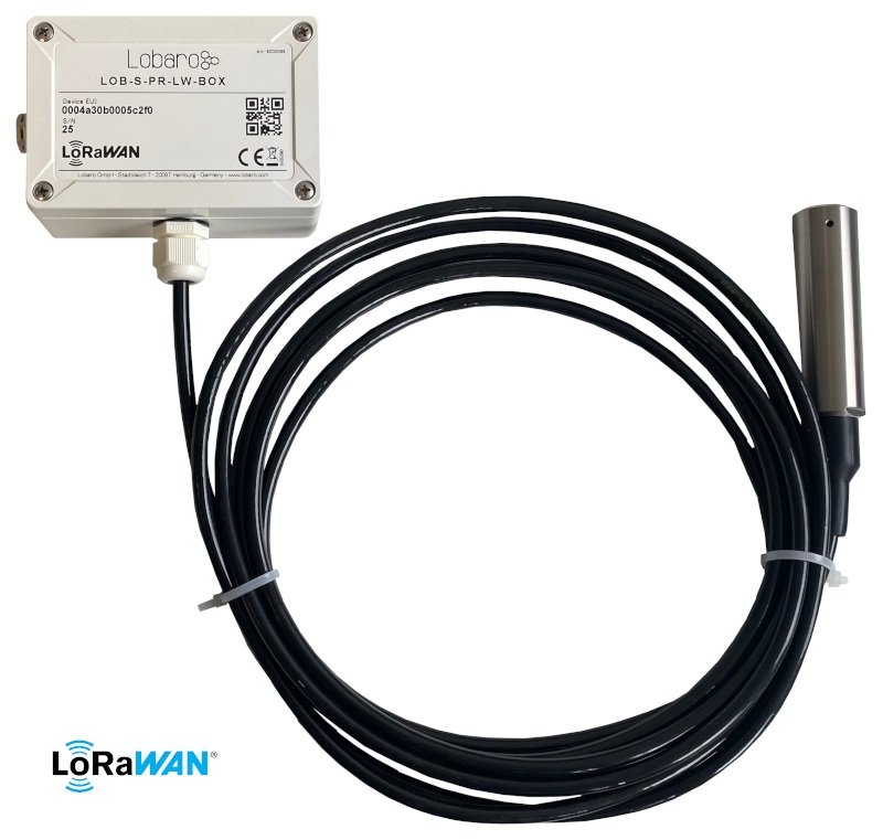
Water Level Sensor (LoRaWAN)
Sensors purchased in 2022 or later are based on the newer Hybrid Industrial Gateway hardware.
Configuration information for the newer Modbus-based pressure sensor is available under Pressure Sensor Application.
Major differences:
- The newer probes communicate via Modbus.
- This discontinued version supports I2C pressure probes only.
- Modbus enables cable lengths of more than 15 m.
- The newer version supports uploads via NB-IoT and LoRaWAN.
Different pressure probes use different communication interfaces. Therefore, several hardware and firmware variants of this product exist.
Install only firmware that is intended for the pressure probe and hardware variant used by your device.
Target Measurement and Purpose
The Water Level Sensor provides precise liquid-level measurements, for example in tanks, and transmits the results via LoRaWAN.
Features
- Cable length: 15 m
- Measurement range: 0–15 mH₂O
- Maximum pressure: approximately 1.5 bar
- Resolution: ±0.5% FSO
- Long-term stability: ±0.3% FSO per year
- Waterproof IP67 housing
- Multi-year battery life
- Ultra-low-power design
Order Information
| Property | Value |
|---|---|
| Product type | LOB-S-PR-LW-BOX |
| Lobaro article number | 8000089 |
Initial Configuration
The initial configuration is normally performed using the
Lobaro Maintenance Tool and the Lobaro USB Configuration Adapter.
The configuration can also be read or changed remotely using LoRaWAN downlink messages.
Specifications
| Property | Value |
|---|---|
| Measurement range | 0–15 mH₂O |
| Equivalent pressure range | Approximately 0–1.5 bar |
| Accuracy | ±0.5% FSO |
| Accuracy in pressure | ±0.0075 bar / ±7.5 mbar |
| Accuracy in water level | ±75 mm / ±7.5 cm |
| Measurement principle | Relative pressure measurement |
| Probe cable | 15 m, including cable feedthrough |
| Probe temperature sensor | Included |
| Supply voltage | 3.6 V |
| Power connector | JST-XH |
| Housing protection | IP67 |
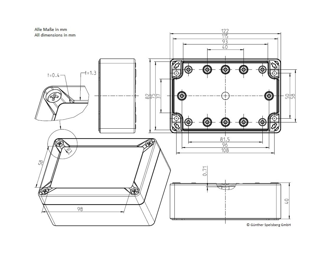
| Housing dimensions | 122 mm × 82 mm × 55 mm |
| Pressure compensation | DAE pressure-compensating element |
| Housing closure | Quick-release screws |
| Operating temperature | -10 °C to +55 °C |
| Relative humidity | 20–70%, non-condensing |
LoRaWAN Connection
The device uses the Lobaro LoRaWAN stack.
Some LoRaWAN features, including LoRaWAN 1.1 and remote configuration, are available only in newer firmware versions:
- Lobaro pressure sensor firmware: version
0.2.1or newer - Keller pressure sensor firmware: version
0.3.0or newer
Use the most recent firmware version compatible with the installed hardware whenever possible.
The LoRaWAN parameters must match the selected LoRaWAN network. Incorrect credentials or activation settings prevent the device from joining the network and transmitting data.
For more information, see the LoRaWAN configuration article.
LoRaWAN Parameters
| Name | Description | Type | Values |
|---|---|---|---|
OTAA | Selects OTAA or ABP activation | bool | true = OTAA, false = ABP |
DevEUI | Unique device identifier | byte[8] | Example: 0123456789abcdef |
JoinEUI | JoinEUI used for OTAA; called AppEUI in LoRaWAN 1.0 | byte[8] | Example: 0123456789abcdef |
AppKey | Application key used for OTAA | byte[16] | LoRaWAN 1.0 and 1.1 |
NwkKey | Network key used for OTAA | byte[16] | LoRaWAN 1.1 only |
SF | Initial or maximum spreading factor | int | 7–12 |
ADR | Enables Adaptive Data Rate | bool | true or false |
TimeSync | Interval between time synchronizations | int | Days; 0 disables synchronization |
RndDelay | Maximum random delay before transmission | int | Seconds |
RemoteConf | Enables remote configuration | bool | true or false |
LostReboot | Reboots after a specified period without downlinks | int | Days; 0 disables the reboot |
Measurement Configuration
The following parameters define the measurement and transmission behavior.
The minimum and maximum values are configured before delivery. Using Restore Default resets them to standard values. They must then be restored using the values printed on the sensor or supplied with the device.
| Name | Description | Typical value |
|---|---|---|
sendCron | Cron expression defining when measurements are read and sent | 0 0/15 * * * * for every 15 minutes |
rangeMin | Minimum measurement range in mH₂O | 0 |
rangeMax | Maximum measurement range in mH₂O | 15 |
outputMin | Minimum digital sensor output | 819 |
outputMax | Maximum digital sensor output | 11664 |
For more information about schedules, see the Introduction to Cron expressions.
Payload Format
Data Message
| Property | Value |
|---|---|
| LoRaWAN port | 1 |
| Legacy payload length | 8 bytes |
Payload length since firmware 0.3.3 | 16 bytes |
| Transmission schedule | Defined by sendCron |
The data message is sent whenever the configured Cron expression triggers.
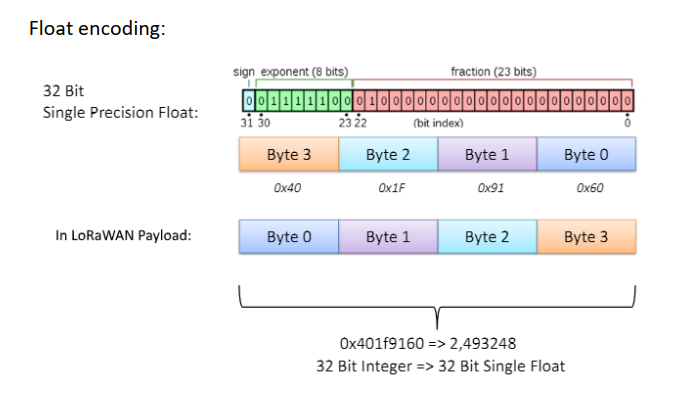
Non-ADC values are encoded in little-endian byte order. The two raw ADC values are encoded in big-endian byte order.
PPPPTTVVppttMMMM
| Field | Byte range | Length | Encoding | Description |
|---|---|---|---|---|
PPPP | 0–3 | 4 bytes | float32 LE | Pressure in bar |
TT | 4–5 | 2 bytes | int16 LE | Probe temperature in 1/100 °C |
VV | 6–7 | 2 bytes | uint16 LE | Device supply voltage in mV |
pp | 8–9 | 2 bytes | uint16 BE | Raw pressure ADC value; firmware 0.3.3 or newer |
tt | 10–11 | 2 bytes | uint16 BE | Raw temperature ADC value; firmware 0.3.3 or newer |
MMMM | 12–15 | 4 bytes | float32 LE | Water level in metres H₂O; firmware 0.3.3 or newer |
Pressure and Water-Level Conversion
- 1.0 bar corresponds approximately to 10 m of water above the probe.
- 0.1 bar corresponds approximately to 1 m of water above the probe.
An external bar-to-metres-head converter can be used for approximate conversions.
Data Message Example
Payload:
cf91873b56076a0e
Decoded values:
PPPP: cf91873b
      -> 0.0041372548 bar
      -> approximately 41 mm water level

TT:   5607
      -> 0x0756
      -> 1878
      -> 18.78 °C

VV:   6a0e
      -> 0x0e6a
      -> 3690 mV
      -> 3.69 V
This example uses the legacy 8-byte data-message format.
Status Message
| Property | Value |
|---|---|
| LoRaWAN port | 64 |
| Payload length | 13 bytes |
| Available since | Firmware 0.3.0 |
| Transmission interval | Once per day |
The status message contains diagnostic information about the device, including the firmware version, latest reset reason, supply voltage, and internal temperature.
All multi-byte values in the status message are encoded in big-endian byte order.
PPBvvvSRFVVTT
| Field | Byte range | Length | Encoding | Description |
|---|---|---|---|---|
PPB | 0–2 | 3 bytes | ASCII | Firmware identifier, always PPB |
vvv | 3–5 | 3 bytes | uint8[3] | Firmware version, for example 0.3.1 |
S | 6 | 1 byte | uint8 | Status or error code |
R | 7 | 1 byte | uint8 | Reset reason |
F | 8 | 1 byte | uint8 | Final words code |
VV | 9–10 | 2 bytes | uint16 BE | Supply voltage in mV |
TT | 11–12 | 2 bytes | int16 BE | Internal temperature in 1/10 °C |
Status Message Example
Payload:
5050420003010006000e6a00d0
Decoded values:
505042 -> ASCII firmware identifier "PPB"
000301 -> Firmware version 0.3.1
00     -> Status code 0: OK
06     -> Reset reason 6: EXTERNAL_RESET_PIN_RESET
00     -> No final words
0e6a   -> 3690 mV -> 3.69 V
00d0   -> 208 -> 20.8 °C
Status Codes
The status code indicates problems detected by the device.
| Hex | Decimal | Name | Description |
|---|---|---|---|
0x00 | 0 | OK | No problems detected |
0x65 | 101 | PROBE_ERROR | Communication with the pressure probe failed |
Reset Reason Codes
The reset-reason value indicates what triggered the latest restart. The restart may have occurred a long time before the current status message was sent.
| Hex | Decimal | Name |
|---|---|---|
0x01 | 1 | LOW_POWER_RESET |
0x02 | 2 | WINDOW_WATCHDOG_RESET |
0x03 | 3 | INDEPENDENT_WATCHDOG_RESET |
0x04 | 4 | SOFTWARE_RESET |
0x05 | 5 | POWER_ON_RESET |
0x06 | 6 | EXTERNAL_RESET_PIN_RESET |
0x07 | 7 | OBL_RESET |
Final Words
The final-words field is currently not used by this firmware.
Supply Voltage
The device measures its supply voltage to help diagnose the condition of the battery.
The voltage is transmitted as an unsigned 16-bit big-endian value in millivolts.
| Property | Value |
|---|---|
| Maximum voltage | 3.7 V |
| Minimum voltage | 2.6 V |
Internal Temperature
The device contains an onboard temperature sensor for diagnostic purposes.
This is not the same sensor as the temperature sensor inside the attached pressure probe. The probe temperature is transmitted in the data message, whereas the onboard temperature is transmitted in the status message.
The internal temperature is encoded as a signed 16-bit big-endian value in tenths of a degree Celsius.
Payload Parser
The Lobaro reference JavaScript parser supports:
- Lobaro IoT Platform
- The Things Network
- ChirpStack
- niota.io
Open the Lobaro Water Level Sensor parser on GitHub
A separate parser is also available for Element IoT:
Open the Element IoT parsers on GitHub
Device and Probe Dimensions

CE Declaration of Conformity
Download the CE Declaration of Conformity
Disposal and WEEE
For information about disposal and recycling, see WEEE Disposal.