Modbus ASCII / RTU Bridge (LoRaWAN)
Firmware compatibility
Newer firmware versions use a different configuration and uplink format than older releases.
- For firmware
0.3.x, refer to the corresponding legacy manual. - For firmware
0.1.x, refer to the legacy PDF manual. - When upgrading the firmware, update both the device configuration and the payload parser in your backend.
The Lobaro Modbus LoRaWAN Bridge connects Modbus ASCII or Modbus RTU devices on an RS-485 bus to a LoRaWAN network.
Key Features
- LoRaWAN 1.0.x network-server support
- Experimental LoRaWAN 1.1 support
- LoRaWAN Class A and Class C operation
- LoRaWAN time synchronization
- Modbus ASCII and Modbus RTU support
- Reading of coils, discrete inputs, input registers, and holding registers
- Writing of coils and holding registers
- Scheduled Modbus readouts
- Modbus commands through LoRaWAN downlinks
- Configuration through USB or LoRaWAN remote configuration
- Interactive Modbus dialog mode through USB
- Listen-before-talk operation alongside another Modbus master
- Managed power-supply output for attached sensors
- Compact payload formats for installations with many registers
Purpose
The Bridge operates as a Modbus master/client on an RS-485 bus. It can regularly execute configured Modbus commands and upload the responses through LoRaWAN.
It can also receive Modbus commands through LoRaWAN downlinks, forward them to the connected Modbus device, and return the response through an uplink.
The Bridge supports:
- Class A for power-efficient battery operation
- Class C for faster downlink response times

Typical applications include:
- Electricity meters
- Water meters
- Heat controllers
- Temperature and humidity sensors
- Industrial machines
- Solar installations
- Building-management equipment
Modbus TCP
This product supports Modbus ASCII and Modbus RTU over RS-485.
Modbus TCP is not supported.
Supported Devices
The Bridge can communicate with Modbus RTU or ASCII slave/server devices that use compatible serial settings.
Devices previously tested with the Bridge include:
| Device | Type | Manufacturer |
|---|---|---|
| Octave Ultrasonic Meter | Water meter | Arad Group |
| ECL Controller | Heating and hot-water controller | Danfoss |
| UMD 97 | Smart-grid power meter | PQ Plus |
| DRS458DE | Power meter | B+G E-Tech |
| PCE-P18 | Humidity and temperature transmitter | PCE Instruments |
Product Variants
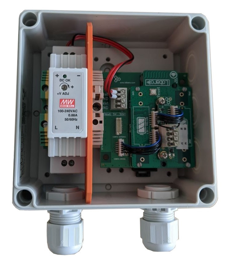
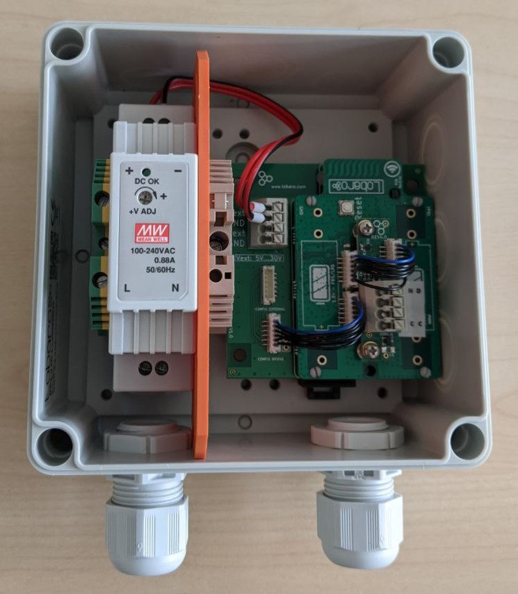
Externally Powered Variant
Type: LOB-GW-MODBUS-LW-PWR
| Item | Order number |
|---|---|
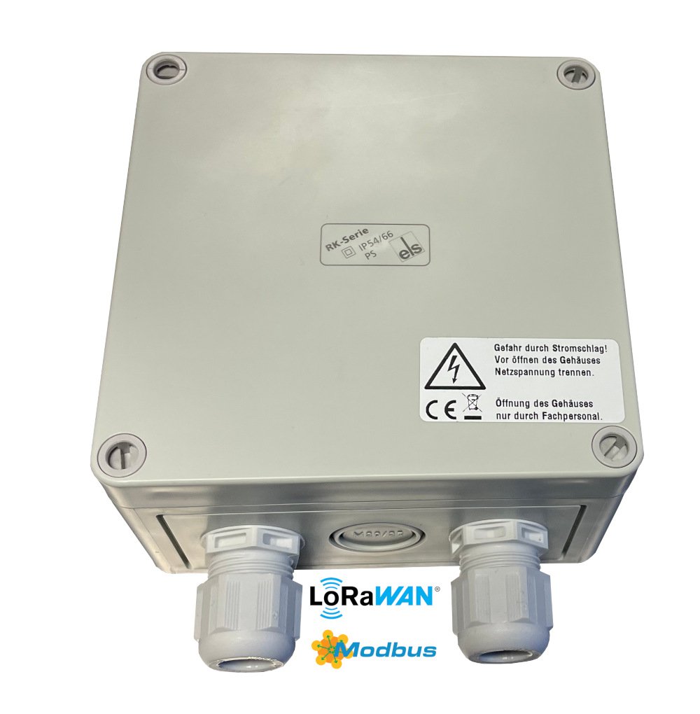
| Modbus LoRaWAN Bridge with external 230 V supply and internal antenna | 8000137 |
| Modbus LoRaWAN Bridge for DIN rail, without housing | 8000043 |
| DR-15-5 DIN-rail power supply, 5 V | 3000006 |
| RK 4/12-L DIN-rail housing | 3000005 |
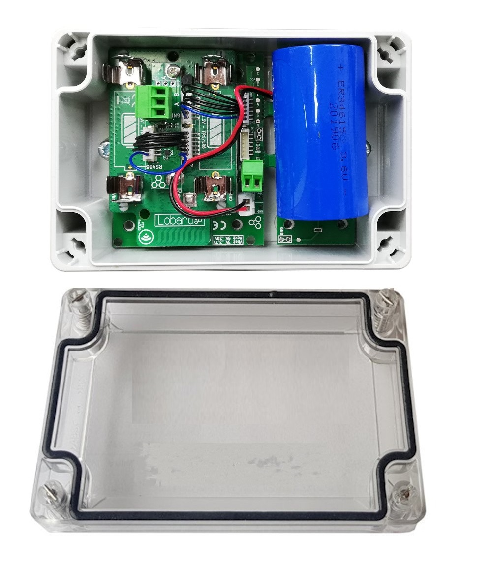
Battery-Powered Variant
Type: LOB-GW-MODBUS-LW
| Item | Order number |
|---|---|
| Modbus LoRaWAN Bridge with battery connector, external-power input, and IP67 housing | 8000041 |
| ER34615 3.6 V D-cell battery with XH connector | 3000169 |
The product image may not show the M8 cable gland.
Custom Variants
Custom variants were available with options such as:
- External antenna
- AA batteries
- Alternative housings
- Alternative power supplies
- NB-IoT instead of LoRaWAN
Quick Start
This example reads three consecutive holding registers from a single Modbus device.
-
Connect the RS-485 lines:
- Bridge
Ato deviceA - Bridge
Bto deviceB - Bridge
GNDto deviceGND, when available
- Bridge
-
Connect the Bridge to a computer using the Lobaro USB Configuration Adapter.
-
Open the Lobaro Maintenance Tool.
-
Configure the LoRaWAN credentials for your network.
-
Confirm that the Bridge is within range of a LoRaWAN gateway.
-
Configure the serial settings according to the connected Modbus device.
-
Set
MbCmdto the required Modbus command. -
Save the configuration.
-
Open the log view and verify the test readout and subsequent uplink.
Example:
MbCmd = 010300000003
The command consists of:
| Bytes | Meaning |
|---|---|
01 | Modbus slave address 1 |
03 | Read Holding Registers |
0000 | Start at register 0 |
0003 | Read three consecutive registers |
Checksums must not be included in MbCmd. The Bridge adds the required RTU CRC or ASCII LRC automatically.
Work Cycle

Init
After power-up or a reboot, the Bridge performs a self-test and validates its configuration.
A successful self-test is indicated by a slow green LED flash. Invalid configuration values can cause repeated LED flashes followed by a reboot.
Test Reading
After configuration validation, the Bridge executes every configured Modbus command once.
The results are written to the device log but are not uploaded. This allows the installer to verify that the connected Modbus devices can be reached.
LoRaWAN Join
The Bridge connects to the configured LoRaWAN network.
With OTAA, it remains in the join state until joining succeeds. Join requests are repeated with progressively longer intervals.
Data Collection
The Bridge executes the commands configured in MbCmd and collects the responses.
Data Transfer
The responses are transmitted through LoRaWAN. Several uplinks may be required when a large amount of data is read.
A device status message is transmitted at most once per day.
Sleep
After completing the upload, the Bridge enters a low-power state until the next activation defined by MbCron.
Configuration
The initial configuration is normally performed using:
- Lobaro Maintenance Tool
- Lobaro USB Configuration Adapter
When enabled, configuration values can also be read or changed remotely using LoRaWAN downlinks.
LoRaWAN Configuration
The LoRaWAN parameters must match the selected network-server configuration.
| Name | Description | Type | Values |
|---|---|---|---|
OTAA | Selects OTAA or ABP activation | bool | true or false |
DevEUI | Unique device identifier | byte[8] | For example 0123456789abcdef |
JoinEUI | Join identifier for OTAA, formerly called AppEUI | byte[8] | For example 0123456789abcdef |
AppKey | Application key for OTAA | byte[16] | LoRaWAN 1.0 and 1.1 |
NwkKey | Network key for OTAA | byte[16] | LoRaWAN 1.1 |
SF | Initial or maximum spreading factor | int | 7–12 |
ADR | Enables Adaptive Data Rate | bool | true or false |
OpMode | LoRaWAN operating class | string | A or C |
TimeSync | Time-synchronization interval | int | Days; 0 disables synchronization |
RndDelay | Maximum random delay before sending | int | Seconds |
RemoteConf | Enables remote configuration | bool | true or false |
LostReboot | Reboot interval when no downlink is received | int | Days; 0 disables the feature |
For more information, see the LoRaWAN configuration article.
Modbus and UART Configuration
The serial parameters must match the connected Modbus devices.
| Name | Description | Values |
|---|---|---|
MbProt | Modbus protocol | RTU or ASCII |
MbBaud | UART baud rate | For example 9600, 19200, 38400 |
MbDataLen | UART data length | 7, 8, or 9 |
MbStopBits | UART stop bits | 0.5, 1, 1.5, or 2 |
MbPar | UART parity | NONE, EVEN, or ODD |
MbCron | Schedule for automatic readout | For example 0 0/15 * * * * |
MbCmd | Comma-separated Modbus commands | For example 010300010003 |
PlFmt | Uplink payload format | 1, 4, or 5 |
PlMax | Maximum compact-payload message size | 10–241, subject to LoRaWAN limits |
PlId | Compact-format identifier | 0–127 |
PowerDelay | Sensor power-supply warm-up time | 0–3600 seconds; -1 means always on |
EnDL | Enables Modbus commands by downlink | true or false |
DialogMode | Enables interactive USB dialog mode | true or false |
LbtDuration | Maximum listen-before-talk duration | 0 disables; otherwise seconds |
LbtSilence | Required quiet period before transmitting | 0 disables; otherwise seconds |
PlMax, PlId, and PowerDelay are available in firmware version 1.3.0 or newer.
Modbus Commands
Commands in MbCmd are entered as hexadecimal bytes without spaces or checksums.
Multiple commands are separated by commas:
090300640003,0a0300640003
This example reads holding registers 100–102 from devices 9 and 10.
Any valid byte sequence can be configured, including write commands.
Configured commands are also executed during the startup test reading. Avoid configuring write operations unless this behavior is explicitly intended.
Large Modbus responses may exceed the maximum LoRaWAN payload size. In that case, the response is split into several uplinks.
Listen Before Talk
A standard Modbus installation normally has only one master. The Bridge can optionally share a bus with another master using the listen-before-talk feature.
When enabled, the Bridge:
- Waits for the existing master to communicate.
- Detects when the communication ends.
- Waits for a configured quiet period.
- Sends its own Modbus requests.
LbtDuration defines how long the Bridge waits for activity from the other master.
LbtSilence defines how long the bus must remain quiet before the Bridge starts transmitting.
Example:
LbtDuration = 130
LbtSilence  = 15
This could be used when another master operates approximately every two minutes and communicates for about 30 seconds.
Setting either value to 0 disables listen-before-talk.
Payload Formats
Port Overview
| Direction | Port | PlFmt | Purpose |
|---|---|---|---|
| Uplink | 1 | Any | Status message |
| Uplink | 3 | 1 | Scheduled Modbus responses in verbose format |
| Uplink | 4 | Any | Responses to Modbus downlink commands |
| Uplink | 5 | Any | Continuation of a split response |
| Uplink | 6 | 2 | Deprecated compact format with timestamp |
| Uplink | 7 | 3 | Deprecated compact format without timestamp |
| Uplink | 20–59 | 4 or 5 | Current compact payload format |
| Uplink | 128 | Any | Remote-configuration response |
| Uplink | 129–131 | Any | Split remote-configuration response |
| Downlink | 4 | Any | Modbus commands |
| Downlink | 128 | Any | Remote configuration |
Status Message - Port 1
Status messages report information about the Bridge itself. They are transmitted at most once per day and have a length of 16 bytes.
| Field | Position | Length | Type | Description |
|---|---|---|---|---|
version | 0 | 3 | uint8[3] | Firmware version |
flags | 3 | 1 | uint8 | Internal status flags |
temperature | 4 | 2 | int16 BE | Internal temperature in 0.1 °C |
voltage | 6 | 2 | uint16 BE | Supply voltage in mV |
timestamp | 8 | 5 | uint40 BE | UNIX timestamp |
plFmt | 13 | 1 | uint8 | Configured payload format |
resetReason | 14 | 1 | uint8 | Latest reset reason |
finalWords | 15 | 1 | uint8 | Additional reset information |
resetReason and finalWords are available in firmware version 1.3.0 or newer.
Reset Reasons
| Hex | Decimal | Name | Meaning |
|---|---|---|---|
0x01 | 1 | LOW_POWER_RESET | Supply voltage became critically low |
0x02 | 2 | WINDOW_WATCHDOG_RESET | Window watchdog triggered |
0x03 | 3 | INDEPENDENT_WATCHDOG_RESET | Independent watchdog triggered |
0x04 | 4 | SOFTWARE_RESET | Firmware initiated the reboot |
0x05 | 5 | POWER_ON_RESET | Device power was switched on |
0x06 | 6 | EXTERNAL_RESET_PIN_RESET | Reset pin or configuration adapter triggered the reset |
0x07 | 7 | OBL_RESET | Option-byte loader reset |
0xff | 255 | UNKNOWN | Unknown reset reason |
Final Words
| Hex | Decimal | Name | Meaning |
|---|---|---|---|
0x00 | 0 | NONE | No additional information |
0x01 | 1 | RESET | Intentional firmware reset |
0x02 | 2 | ASSERT | Firmware assertion failed |
0x03 | 3 | STACK_OVERFLOW | Stack overflow |
0x04 | 4 | HARD_FAULT | Processor hard fault |
0x05 | 5 | OUT_OF_MEMORY | Critical memory allocation failed |
0x10 | 16 | INVALID_CONFIG | Invalid configuration detected |
0x11 | 17 | REMOTE_RESET | Reboot requested remotely |
0x12 | 18 | NETWORK_LOST | LoRaWAN connection was considered lost |
0x13 | 19 | NETWORK_FAIL | Network join failed after a remote configuration change |
Verbose Payload Format - Port 3, PlFmt=1
The verbose format contains the complete Modbus response together with information from the command.
Each uplink begins with a five-byte UNIX timestamp followed by one or more response blocks.
Bytes  | 0 1 2 3 4 | 5 ...      | ...        |
Part   | timestamp | response 1 | response 2 |
Each response block has this structure:
Bytes  | 0   | 1 ... len-3     | len-2..len-1  | len   |
Field  | len | Modbus response | start address | count |
| Field | Description |
|---|---|
len | Number of bytes in the response block |
Modbus response | Raw bytes returned by the Modbus device |
start address | First requested register or coil |
count | Number of requested registers or coils |
The additional address and count values allow the backend to identify which part of the Modbus device was queried.
For functions that do not contain a start address or count, these additional values are undefined.
Response to Downlink - Port 4
Responses to Modbus commands received through downlink port 4 use the same verbose format as scheduled responses on port 3.
The timestamp represents the time at which the downlink was received.
Split Responses - Port 5
If a Modbus response does not fit into one LoRaWAN uplink:
- The first part is sent on port 3 or port 4.
- Remaining bytes are sent on port 5.
- The backend must append the port 5 payload to the previous response.
- LoRaWAN frame counters should be checked to detect missing parts.
A split response can require several uplinks when a high spreading factor is used.
To avoid splitting:
- Read fewer registers per command.
- Use a lower spreading factor where appropriate.
- Use a compact payload format.
Deprecated Compact Format - Ports 6 and 7
Payload formats 2 and 3 were used before firmware version 1.3.0.
They have been replaced by the compact format on ports 20-59. Existing installations should migrate to the newer format or remain on a compatible legacy firmware.
Compact Payload Format - Ports 20-59
The compact format transmits only the data portion of successful Modbus responses. It reduces LoRaWAN overhead but requires a parser that already knows the device configuration.
The relevant parameters are:
PlFmtPlMaxPlIdMbCmd
PlFmt=5
The message header is one byte:
bit 7     = error indicator
bits 0–6  = PlId
PlFmt=4
The message header consists of:
1 byte  error indicator and PlId
5 bytes UNIX timestamp, big endian
Error Handling
If a command fails:
- The error bit in the header is set.
- The data bytes reserved for the failed command are filled with
0xff.
Message Distribution
Responses are assigned sequentially to ports 20–59.
PlMax defines the maximum size of each uplink, including its header. The allowed value depends on the configured spreading factor and regional LoRaWAN limits.
No individual command response may exceed PlMax after including the message header.
Remote Configuration - Ports 128–131
When remote configuration is enabled:
- Commands are received through downlink port
128. - Short responses are sent through uplink port
128. - Long responses are split across ports
129,130, and131.
Modbus Commands by Downlink - Port 4
A port 4 downlink can contain one or more Modbus commands.
Each command is prefixed with a one-byte length:
[length][command][length][command]...
The commands are sent as raw bytes without RTU CRC or ASCII LRC.
Example:
06180401000001
Breakdown:
| Bytes | Meaning |
|---|---|
06 | Command length: six bytes |
18 | Slave address 24 |
04 | Read Input Registers |
0100 | Start at register 256 |
0001 | Read one register |
If the addressed device does not respond, the Bridge creates a Modbus exception response with code 11, Gateway Target Device Failed to Respond.
Examples
Read Three Holding Registers
Configuration:
MbCmd = 010300000003
Possible successful uplink on port 3:
005d1698fd0c0103061234567890ab000003
Breakdown:
005d1698fd  timestamp
0c          response length: 12 bytes
01          slave address 1
03          Read Holding Registers
06          six data bytes follow
1234567890ab
0000        start register
03          register count
Possible failed response:
005d1698fd0601830b000003
Here, 83 indicates function 3 with an error flag and 0b indicates that the target device did not respond.
Split Response
Configuration:
MbCmd = 010300010020
The command reads 32 registers and returns 64 data bytes.
The first part is sent on port 3:
005d1698fd46010340000100020003000400050006000700080009000a000b000c000d000e000f001000110012001300140015
The continuation is sent on port 5:
0016001700180019001a001b001c001d001e001f00200120
The application must append the port 5 data to the incomplete response received on port 3.
Compact Format with Timestamp
Configuration:
MbCmd = 010300000003
PlFmt = 4
PlMax = 51
PlId = 0
Successful port 20 uplink:
00005fd8bf08000000010033
Breakdown:
00            no error, PlId 0
005fd8bf08    timestamp
000000010033  data from three registers
Failed port 20 uplink:
80005fd8c7caffffffffffff
The highest header bit indicates an error and the response data is replaced by ff.
Dialog Mode
Dialog Mode provides an interactive Modbus master through the Lobaro Maintenance Tool.
Enable it with:
DialogMode = true
After the device reboots:
- It does not connect to LoRaWAN.
- It does not execute scheduled commands.
- It waits for commands entered through the Maintenance Tool.
- Commands are sent through the Send via UART input field.
- Responses are shown in the device log.
Commands must be entered as hexadecimal bytes without checksums.
Example command:
010300100002
This reads holding registers 16 and 17 from device address 1.
Possible responses:
01830b
The target device did not respond.
018302
The addressed registers are not supported.
010304abcd1234
A successful response containing:
Register 16 = abcd
Register 17 = 1234
Dialog Mode keeps the device active and can quickly discharge the battery.
Do not leave a battery-powered device in Dialog Mode.
Complex Installations
The standard firmware executes all configured commands using one schedule.
Custom firmware may be required when an installation needs:
- Different schedules for different registers
- Several measurements followed by averaging
- Conditional requests based on a status register
- Custom data transformations
- More complex error handling
- Alternative communication such as NB-IoT
Technical Characteristics
Product
| Property | Value |
|---|---|
| Type, 230 V variant | LOB-GW-MODBUS-LW-PWR |
| Type, battery variant | LOB-GW-MODBUS-LW |
| Description | Modbus Bridge with LoRaWAN, external 230 V power, and internal antenna |
RF Transceiver
| Property | Value |
|---|---|
| Transceiver | Semtech SX1272 |
| Frequency | 863–870 MHz |
| Maximum TX power | +13 dBm |
| Typical range | Up to 2 km |
| Ideal range | Up to 10 km with free line of sight |
LoRaWAN
| Property | Value |
|---|---|
| Protocol | LoRaWAN 1.0.2 EU868 |
| Device classes | Class A and Class C |
| LoRaWAN 1.1 | Experimental |
| Activation | OTAA or ABP |
| Encryption | AES-128 |
Modbus
| Property | Value |
|---|---|
| Physical bus | RS-485 twisted pair, optional GND |
| Protocol | Modbus RTU or Modbus ASCII |
| HBM protection | Greater than ±15 kV |
| IEC 61000-4-2 contact-discharge protection | Greater than ±12 kV |
| IEC 61000-4-4 burst protection | Greater than ±4 kV |
| Tested RS-485 cable length | Up to 3 m |
| Longer cables | Possible, but not tested for this product |
Environmental Requirements
| Property | Value |
|---|---|
| Operating temperature | -20 °C to +55 °C |
| Maximum installation height | 2 m |
Standards


CE Declaration of Conformity
Disposal and WEEE
Dispose of the device and its batteries according to the applicable local requirements for electronic equipment. Please refer to: https://www.lobaro.com/entsorgung-weee-rohs/
Reference Decoder
The following decoder supports the status format, verbose Modbus responses, remote-configuration responses, and exposes compact payloads as raw data.
function readUInt16BE(bytes, offset = 0) {
  return (bytes[offset] << 8) | bytes[offset + 1];
}

function readInt16BE(bytes, offset = 0) {
  const value = readUInt16BE(bytes, offset);
  return value & 0x8000 ? value - 0x10000 : value;
}

function readUInt40BE(bytes, offset = 0) {
  return (
    bytes[offset] * 0x100000000 +
    bytes[offset + 1] * 0x1000000 +
    bytes[offset + 2] * 0x10000 +
    bytes[offset + 3] * 0x100 +
    bytes[offset + 4]
  );
}

function bytesToHex(bytes) {
  return bytes
    .map((value) => value.toString(16).padStart(2, '0'))
    .join('');
}

function decodeStatus(bytes) {
  if (bytes.length < 14) {
    return { error: 'Status payload is too short' };
  }

  const result = {
    port: 1,
    version: `v${bytes[0]}.${bytes[1]}.${bytes[2]}`,
    flags: bytes[3],
    temperature: readInt16BE(bytes, 4) / 10,
    voltage: readUInt16BE(bytes, 6) / 1000,
    timestamp: readUInt40BE(bytes, 8),
    payloadFormat: bytes[13],
    noData: Boolean(bytes[3] & 0x01),
  };

  if (bytes.length >= 16) {
    result.resetReason = bytes[14];
    result.finalWords = bytes[15];
  }

  return result;
}

function modbusErrorText(code) {
  const errors = {
    1: 'Illegal Function',
    2: 'Illegal Data Address',
    3: 'Illegal Data Value',
    4: 'Slave Device Failure',
    5: 'Acknowledge',
    6: 'Slave Device Busy',
    7: 'Negative Acknowledge',
    8: 'Memory Parity Error',
    10: 'Gateway Path Unavailable',
    11: 'Gateway Target Device Failed to Respond',
  };

  return errors[code] || 'Unknown error code';
}

function decodeVerboseResponse(raw) {
  if (raw.length < 6) {
    return {
      error: 'Response block is too short',
      raw: bytesToHex(raw),
    };
  }

  const functionCode = raw[1] & 0x7f;
  const isError = Boolean(raw[1] & 0x80);

  const result = {
    slave: raw[0],
    function: functionCode,
    error: isError,
    rawResponse: bytesToHex(raw.slice(0, -3)),
    startAddress: readUInt16BE(raw, raw.length - 3),
    count: raw[raw.length - 1],
  };

  if (isError) {
    result.errorCode = raw[2];
    result.errorText = modbusErrorText(raw[2]);
  }

  return result;
}

function decodeVerbose(bytes, port) {
  if (bytes.length < 5) {
    return { error: 'Verbose payload is too short', port };
  }

  const timestamp = readUInt40BE(bytes, 0);
  const responses = [];
  let offset = 5;

  while (offset < bytes.length) {
    const length = bytes[offset];
    offset += 1;

    if (offset + length > bytes.length) {
      return {
        port,
        timestamp,
        responses,
        split: true,
        remainingLength: length,
        receivedBytes: bytes.length - offset,
      };
    }

    responses.push(
      decodeVerboseResponse(bytes.slice(offset, offset + length)),
    );

    offset += length;
  }

  return {
    port,
    timestamp,
    responses,
  };
}

function decodeTextResponse(bytes) {
  const response = String.fromCharCode(...bytes);

  return {
    response,
    error: response.length === 0 || response.startsWith('!'),
  };
}

function decodeUplink(input) {
  const { fPort, bytes } = input;

  if (fPort === 1) {
    return { data: decodeStatus(bytes) };
  }

  if (fPort === 3 || fPort === 4) {
    return { data: decodeVerbose(bytes, fPort) };
  }

  if (fPort === 5) {
    return {
      data: {
        port: fPort,
        continuation: true,
        raw: bytesToHex(bytes),
      },
    };
  }

  if (fPort >= 20 && fPort <= 59) {
    return {
      data: {
        port: fPort,
        compact: true,
        error: Boolean(bytes[0] & 0x80),
        payloadId: bytes[0] & 0x7f,
        raw: bytesToHex(bytes),
      },
    };
  }

  if (fPort >= 128 && fPort <= 131) {
    return {
      data: {
        port: fPort,
        ...decodeTextResponse(bytes),
      },
    };
  }

  return {
    errors: [`Unsupported LoRaWAN port: ${fPort}`],
  };
}