Manual v0.3.x
Legacy firmware documentation
This manual applies to firmware version v0.3.x of the Modbus LoRaWAN Bridge.
This firmware uses a different configuration and uplink format than newer firmware versions.
Consider using the latest firmware supported by your hardware. When updating, ensure that both the device configuration and the backend payload parser are updated.
Target Measurement and Purpose
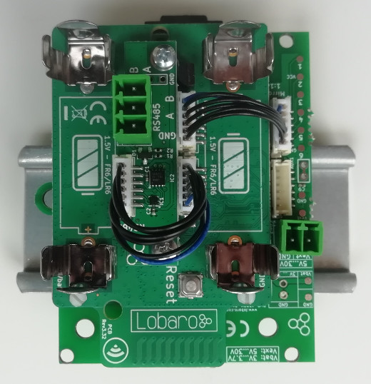
The Lobaro Modbus LoRaWAN Bridge is a low-power device for reading values from external devices via Modbus ASCII or Modbus RTU over an RS-485 interface.
The collected data is transmitted via LoRaWAN and can be processed by an attached backend system.
Typical applications include:
- Reading electricity meters
- Reading water meters
- Retrieving temperature and humidity measurements
- Reading industrial sensors
- Connecting building-management equipment

The Modbus Bridge supports all four standard Modbus object types:
- Coils
- Discrete Inputs
- Holding Registers
- Input Registers
Multiple Modbus devices on the same RS-485 bus can be accessed by one Bridge. Readout intervals and register definitions can be configured according to the installation requirements.
Datasheet
The legacy technical datasheet can be provided as a downloadable PDF:
Download the Modbus LoRaWAN datasheet
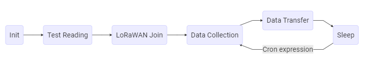
Work Cycle
The Modbus LoRaWAN Bridge spends most of its operating time in deep sleep to conserve energy.
For each scheduled readout, the Bridge:
- Wakes up.
- Reads the configured Modbus devices.
- Uploads the collected data via LoRaWAN.
- Returns to deep sleep.
Initialization
When the device starts after connecting a power supply or after a reboot, it enters the initialization state.
During initialization:
- A short self-test is performed.
- A successful self-test is indicated by one slow green LED flash.
- The configuration is parsed and validated.
- Invalid configuration values cause the LED to flash three times.
- The device then reboots and repeats the configuration check.
The device does not continue normal operation until the configuration is valid.
Configuration
The initial configuration is performed using:
- Lobaro Maintenance Tool
- Lobaro USB Configuration Adapter
LoRaWAN Parameters
The LoRaWAN parameters must match the target LoRaWAN network.
The firmware supports:
- Over-the-Air Activation, OTAA
- Activation by Personalization, ABP
Byte-array values are entered as hexadecimal strings without a 0x prefix.
For example, an eight-byte DevEUI is represented by 16 hexadecimal characters:
0123456789abcdef
| Name | Activation | Type | Description |
|---|---|---|---|
OTAA | Both | bool | true uses OTAA; false uses ABP |
DevEUI | OTAA | hexbyte[8] | Unique device identifier used during the join operation |
AppEUI | OTAA | hexbyte[8] | Identifier of the application in the LoRaWAN network |
AppKey | OTAA | hexbyte[16] | Key used for LoRaWAN network activation |
AppSKey | ABP | hexbyte[16] | Application Session Key |
NetSKey | ABP | hexbyte[16] | Network Session Key |
DevAdr | ABP | hexbyte[4] | Device address used by the LoRaWAN network |
SF | Both | int | Initial spreading factor from 7 to 12 |
ADR | Both | bool | Enables or disables Adaptive Data Rate |
The factory-defined DevEUI is globally unique and should normally not be changed.
Modbus and UART Parameters
The serial configuration must match the connected Modbus devices.
Refer to the documentation of the attached Modbus devices when selecting these values.
| Name | Description | Example values |
|---|---|---|
ModbusProtocol | Modbus protocol | RTU, ASCII |
ModbusBaud | UART baud rate | 9600, 19200, 38400 |
ModbusDataLendth | UART data length | 7, 8, 9 |
ModbusStopBits | UART stop bits | 0.5, 1, 1.5, 2 |
ModbusParity | UART parity | NONE, EVEN, ODD |
The configuration key is named ModbusDataLendth in this legacy firmware, including the spelling shown above.
Operation
| Name | Description | Example |
|---|---|---|
ModbusCron | Cron expression defining when the Modbus devices are read | 0 0/15 * * * * for every 15 minutes |
For more information, see the Cron configuration.
Register and Coil Definitions
The firmware provides one configuration value for each Modbus object type.
| Configuration | Modbus object | Function code |
|---|---|---|
Coils | One-bit read/write values | 0x01 |
DiscreteInputs | One-bit read-only values | 0x02 |
HoldingRegisters | 16-bit read/write registers | 0x03 |
InputRegisters | 16-bit read-only registers | 0x04 |
Each individual definition consists of three values separated by colons:
device-address:start-address:count
The values have the following meaning:
-
Device address Modbus address of the device to read. Valid addresses range from
1to247. -
Start address Address of the first coil or register. Valid values range from
0to65535. -
Count Number of consecutive coils or registers to read. The maximum supported value is
127.
Reading more than approximately 22 registers in one request can result in payloads that cannot be transmitted completely at high LoRaWAN spreading factors.
Multiple definitions are separated by commas without spaces:
1:0:3,2:100:5
Unused object types should be configured as an empty string.
Invalid definitions prevent normal device operation. The Bridge reports the invalid configuration and reboots until the configuration is corrected.
Examples
| Definition | Meaning |
|---|---|
1:0:3 | Read the first three coils or registers from device 1 |
2:40001:1,2:2000:10 | Read address 40001 and addresses 2000–2009 from device 2 |
4:0:2,5:0:2,5:20:1 | Read addresses 0–1 from device 4, and addresses 0–1 and 20 from device 5 |
Payload Formats
The Modbus Bridge uses different LoRaWAN ports for the different message types.
| Port | Message |
|---|---|
1 | Device status message |
11 | Coil data, Modbus function 0x01 |
12 | Discrete Input data, Modbus function 0x02 |
13 | Holding Register data, Modbus function 0x03 |
14 | Input Register data, Modbus function 0x04 |
Status Message
Status messages are transmitted on LoRaWAN port 1.
A status message is sent together with measurement data, but no more than once per day.
The payload has a fixed length of 14 bytes.
| Field | Position | Length | Type | Description |
|---|---|---|---|---|
version | 0 | 3 | uint8[3] | Firmware version |
flags | 3 | 1 | uint8 | Internal status flags |
temperature | 4 | 2 | int16 BE | Internal device temperature in 0.1 °C |
voltage | 6 | 2 | uint16 BE | Supply voltage in millivolts |
timestamp | 8 | 5 | uint40 BE | UNIX timestamp at message creation |
mode | 13 | 1 | uint8 | Device operating mode |
Example values:
| Field | Raw value | Decoded value |
|---|---|---|
version | [1, 0, 4] | v1.0.4 |
temperature | 246 | 24.6 °C |
voltage | 3547 | 3.547 V |
timestamp | 1533055905 | UNIX timestamp |
Data Messages
The general message format is identical for all four Modbus object types.
The LoRaWAN port identifies the object type that was read.
Each message starts with a five-byte UNIX timestamp, followed by one or more data packages.
Each data package represents one configured Modbus read operation.
General Structure
timestamp | data package 1 | data package 2 | ...
The timestamp is encoded as an unsigned 40-bit big-endian value.
Data Package Structure
| Field | Position | Length | Type | Description |
|---|---|---|---|---|
address | 0 | 1 | uint8 | Modbus address of the device |
start | 1 | 2 | uint16 BE | Address of the first coil or register |
countAndError | 3 | 1 | uint8 | Error flag and number of values |
data | 4 | Variable | uint8[] | Raw data returned by the Modbus device |
The highest bit of countAndError indicates whether an error occurred.
- Bit 7 set to
0: readout successful - Bit 7 set to
1: readout failed - Bits 0–6: number of coils or registers requested
The count can be extracted with:
countAndError & 0x7f
The error state can be extracted with:
Boolean(countAndError & 0x80)
Data Length
For Coils and Discrete Inputs on ports 11 and 12:
dataLength = ceil(count / 8)
For Holding Registers and Input Registers on ports 13 and 14:
dataLength = count * 2
The data bytes contain the raw values returned by the Modbus device. Their interpretation depends on the attached device and its register documentation.
When an error occurs, the data bytes may still be present, but their content is undefined.
Complex Installations
The standard firmware reads all configured values according to one common schedule.
A custom firmware may be required for installations that need:
- Different schedules for different registers
- Multiple measurements followed by averaging
- Conditional readouts based on a status register
- Writing values to coils or registers
- Custom payload processing
- Alternative communication such as NB-IoT
Technical Characteristics
Product
| Property | Value |
|---|---|
| Type | Modbus485-LoRaWAN |
| Description | Modbus over LoRaWAN Bridge |
RF Transceiver
| Property | Value |
|---|---|
| Transceiver | Semtech SX1272 |
| Frequency | 863–870 MHz |
| Maximum transmission power | +14 dBm |
| Typical range | Up to 2 km |
| Ideal range | Up to 10 km with free line of sight |
LoRaWAN
| Property | Value |
|---|---|
| Protocol | LoRaWAN 1.0.1 EU868 |
| Device class | Class A |
| Activation | OTAA or ABP |
| Encryption | AES-128 |
Modbus
| Property | Value |
|---|---|
| Physical interface | RS-485 twisted pair, with optional GND |
| Supported protocols | Modbus RTU and Modbus ASCII |
Environmental Requirements
| Property | Value |
|---|---|
| Operating temperature | -20 °C to +55 °C |
| Maximum installation height | 2 m |
CE Declaration of Conformity
Download the CE Declaration of Conformity
Disposal and WEEE
Dispose of the device and its batteries according to the applicable local requirements for waste electrical and electronic equipment.
Reference Decoder
The following JavaScript decoder can be used as a starting point for The Things Network or similar LoRaWAN backends.
function readVersion(bytes) {
  if (!bytes || bytes.length < 3) {
    return null;
  }

  return `v${bytes[0]}.${bytes[1]}.${bytes[2]}`;
}

function readUInt16BE(bytes, offset = 0) {
  return (bytes[offset] << 8) | bytes[offset + 1];
}

function readInt16BE(bytes, offset = 0) {
  const value = readUInt16BE(bytes, offset);
  return value & 0x8000 ? value - 0x10000 : value;
}

function readUInt40BE(bytes, offset = 0) {
  return (
    bytes[offset] * 0x100000000 +
    bytes[offset + 1] * 0x1000000 +
    bytes[offset + 2] * 0x10000 +
    bytes[offset + 3] * 0x100 +
    bytes[offset + 4]
  );
}

function decodeStatus(bytes) {
  if (bytes.length < 14) {
    return {
      error: 'Status payload is too short',
    };
  }

  return {
    port: 1,
    version: readVersion(bytes),
    flags: bytes[3],
    temperature: readInt16BE(bytes, 4) / 10,
    voltage: readUInt16BE(bytes, 6) / 1000,
    timestamp: readUInt40BE(bytes, 8),
    operationMode: bytes[13],
  };
}

function decodeData(bytes, port) {
  if (bytes.length < 5) {
    return {
      error: 'Data payload is too short',
      port,
    };
  }

  const functionCode = port - 10;
  const values = [];
  let offset = 5;

  while (offset + 4 <= bytes.length) {
    const device = bytes[offset];
    const start = readUInt16BE(bytes, offset + 1);
    const countAndError = bytes[offset + 3];
    const count = countAndError & 0x7f;
    const error = Boolean(countAndError & 0x80);

    const dataLength =
      functionCode <= 2
        ? Math.ceil(count / 8)
        : count * 2;

    if (offset + 4 + dataLength > bytes.length) {
      return {
        port,
        function: functionCode,
        timestamp: readUInt40BE(bytes, 0),
        values,
        error: 'Incomplete data package',
      };
    }

    values.push({
      device,
      start,
      count,
      error,
      data: bytes.slice(offset + 4, offset + 4 + dataLength),
    });

    offset += 4 + dataLength;
  }

  return {
    port,
    function: functionCode,
    timestamp: readUInt40BE(bytes, 0),
    values,
  };
}

function Decoder(bytes, port) {
  switch (port) {
    case 1:
      return decodeStatus(bytes);

    case 11:
    case 12:
    case 13:
    case 14:
      return decodeData(bytes, port);

    default:
      return {
        error: 'Invalid port',
        port,
      };
  }
}