EDL21 Electricity Meter Bridge (LoRaWAN)
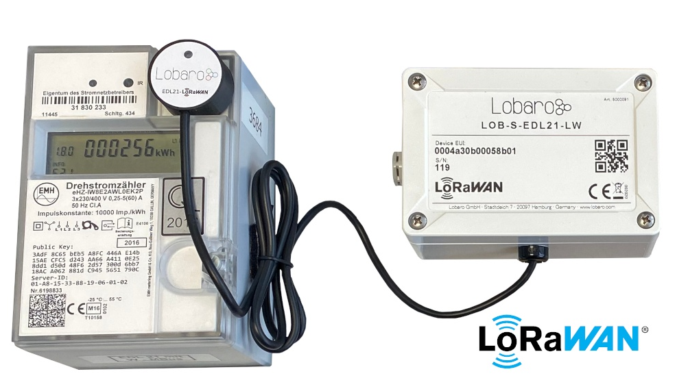
The EDL21 over LoRaWAN bridge is a device that can be used to read out modern utility meters with a standardized infrared "INFO" interface.
These types of meters are called "EDL21"-compatible in Germany — hence the name. The meter outputs a serial protocol conforming to the Smart Message Language Protocol 1.04 (SML) over its infrared "INFO" interface. This interface is intended to be used by end-users and not for billing purposes of the electricity supplier. The read information normally contains the current consumption values of the meter and gets interpreted and forwarded by the EDL21 bridge via a LoRaWAN network to web-based applications interested in further processing this data.
Top Features
- LoRaWAN 1.0.x and 1.1 network servers supported
- LoRaWAN time synchronisation
- Configuration via USB or remotely via LoRaWAN downlink
- Compatible with many electrical utility meters
- Configure up to 25 OBIS codes to be read
- RGB status LED
- Variant with external power supply available on request
- Separation of infrared readout head and LoRaWAN antenna possible
Compatible Utility Meters
Any meter that adheres to the standard can be read. The following list contains meters that we have successfully tested.
| Electricity meter | Manufacturer |
|---|---|
| DTZ541-ZEBA | Holley |
| LK13 series | Logarex |
| OpenWay® 3.HZ | iTron |
| SGM-C4 series | efr |
| SGM-D series | efr |
| eHZ-K series | EMH |
| mMe4.0 series | EMH |
| ED300 series | EMH |
| eBZD series | EMH |
| E320 | Landis+Gyr |
| MT681 | ISKRA |
Product Variants
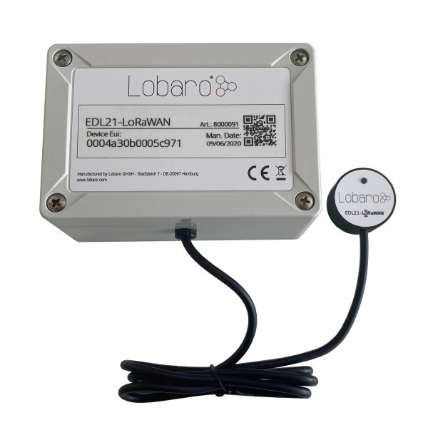
EDL21-LoRaWAN Bridge (universal head, XH battery connector, int. Ant.),
order number: 8000091.
Quickstart
-
Connect to the device with the Lobaro Maintenance Tool using the Lobaro Config Adapter.
-
Under Configuration click "Reload Config" and change the fields
ReadCronandObisCodeas needed, followed by clicking "Write to Device". An example configuration is shown below.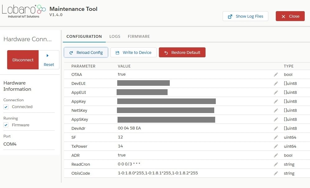
-
Register the device in your LoRaWAN network.
-
Connect an ER34614 3.6 V D-cell battery via the XH connector, or connect an external power supply.
-
If not connected to anything, the red LED will start blinking as long as no data is received; after 1 minute it will sleep for 15 seconds after every 5 retries.
-
Tighten the screws and install the bridge beside your electric meter.
-
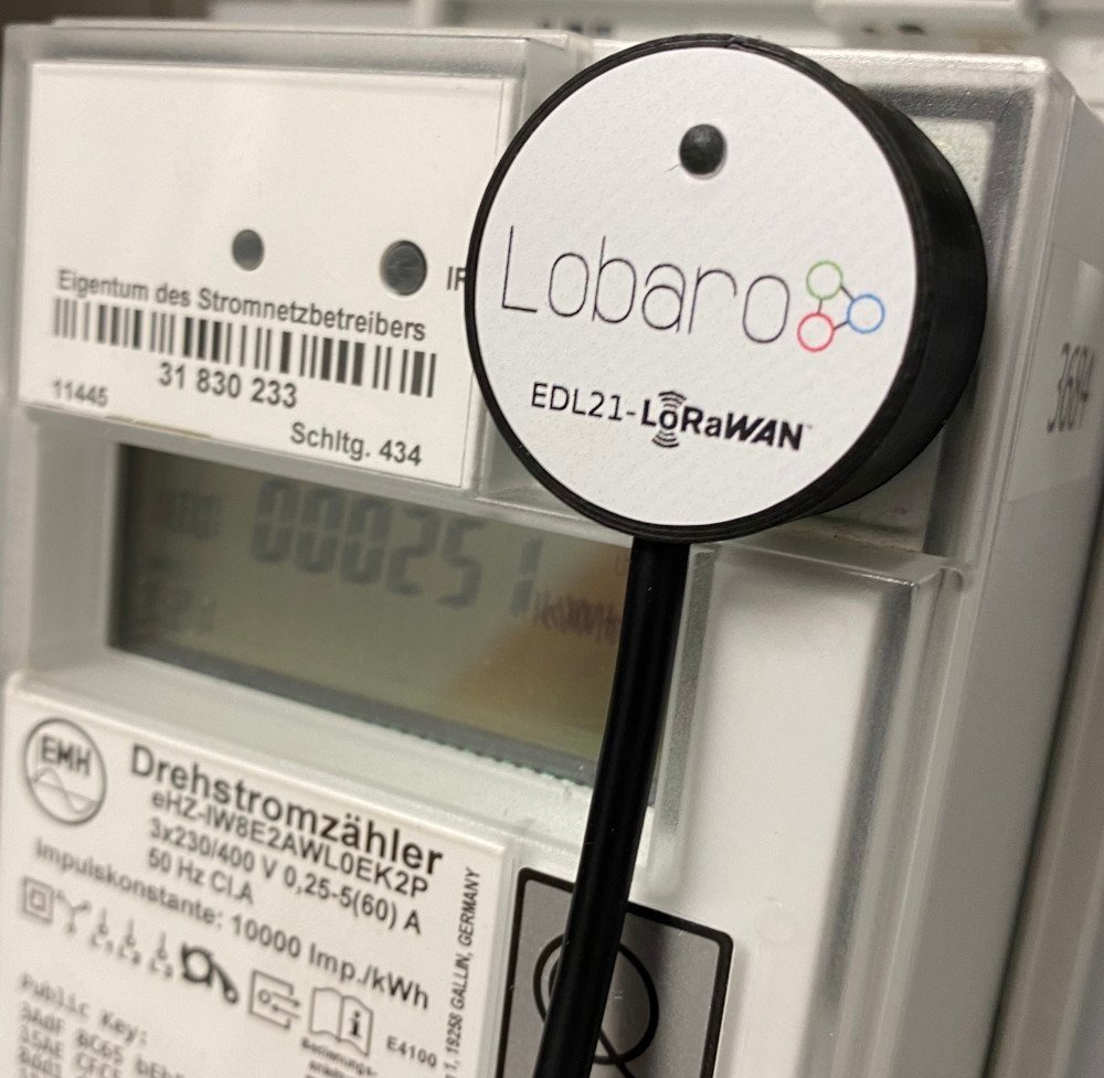
Place the EDL21 opto head on the "INFO" interface.
-
As soon as the EDL21 receives data, its green LED will light up for 5 seconds; when connected to a LoRaWAN network, its blue LED will light up for 5 seconds.
-
Check the sent data (port 3). If the payload is zero, the EDL21 was not able to read data — recheck the proper alignment.
Configuration
The configuration is done using the Lobaro Maintenance Tool and the Lobaro USB PC adapter.
Available firmware versions and release notes are listed on the Firmware & Changelog page.
LoRaWAN
The connection to the LoRaWAN network is defined by multiple configuration parameters. These need to be set according to your LoRaWAN network and the way your device is supposed to be attached to it, or the device will not be able to send any data.
| Name | Description | Type | Values |
|---|---|---|---|
OTAA | Activation: OTAA or ABP | bool | true = use OTAA, false = use ABP |
DevEUI | DevEUI used to identify the device | byte[8] | e.g. 0123456789abcdef |
JoinEUI | Used for OTAA (called AppEUI in v1.0) | byte[8] | e.g. 0123456789abcdef |
AppKey | Key used for OTAA (v1.0 and v1.1) | byte[16] | |
NwkKey | Key used for OTAA (v1.1 only) | byte[16] | |
SF | Initial / maximum spreading factor | int | 7-12 |
ADR | Use Adaptive Data Rate | bool | true = use ADR, false = don't |
TimeSync | Days after which to sync time | int | days, 0 = don't sync time |
RndDelay | Random delay before sending | int | max seconds |
RemoteConf | Not supported by this firmware | bool | false = deactivate |
LostReboot | Days without downlink before reboot (triggers downlinks) | int | days, 0 = don't reboot |
Operation
Configuration values defining the behaviour of the device.
| Name | Description | Example value |
|---|---|---|
ReadCron | Cron expression defining when to read | 0 0/15 * * * * for every 15 minutes |
ObisCode | Comma-separated list of OBIS codes to select a subset of the available information | 1-0:1.7.255*255 = Leistung (Momentan) |
PayloadFormat | Format used for data upload (include timestamps or not) | 1 = no timestamp, 2 = include timestamp |
See also our Introduction to CRON expressions and our Introduction to OBIS codes.
LED Blinking Patterns
The following patterns are explained in the order in which they appear after the initial power-on / reset of the device.
| Color | Duration | Description |
|---|---|---|
red/green/blue | 300 ms each | Initial pattern after reset |
red/green | 1 s | New in 0.3.2: single readout success/failure before OTAA join |
red | short, blinking | Trying to receive meter optical data for the first time after OTAA join |
green | 5 seconds | Successfully received meter optical data |
blue | 5 seconds | LoRaWAN network join |
blue | short | Sending LoRaWAN data uplink |
off | – | Low-power mode until the next send-out cycle |
As you can see from this, the device will start the LoRaWAN join only after receiving optical data at least once.
Payload
Status Packet (Port 1)
Once per day a status packet is sent. It contains basic information about the device. The battery voltage is transmitted in 1/1000 V and the temperature in 1/10 °C. Both are in big-endian byte order.
| Version Major | Version Minor | Version Patch | Flags | Battery Voltage | Temperature |
|---|---|---|---|---|---|
| 1 byte | 1 byte | 1 byte | 1 byte | 2 byte | 2 byte |
| unsigned | unsigned | unsigned | unsigned | unsigned | signed |
Payload Format 1 (default, Port 3, with exponent)
This format is used when the configuration parameter PayloadFormat is set to
1 (which is the default value).
The payload consists of multiple entries, one entry per OBIS code given in the configuration. Each entry follows this structure:
| OBIS code (hex) | length of value (n) | value | exponent |
|---|---|---|---|
| 6 bytes | 1 byte | n bytes, LSB first | 1 byte (signed) |
Example packet: 01 00 01 08 00 FE 08 FF 01 00 00 00 00 00 00 ff 01 00 01 08 00 FE 08 FF 02 00 00 00 00 00 00 02
Entry 1:
| OBIS code (hex) | length of value (n) | value | exponent |
|---|---|---|---|
| 01 00 01 08 00 FE | 08 | FF 01 00 00 00 00 00 00 | ff |
| 1-0:1.8.0*254 | 8 | 511 | -1 |
Value = 511 × 10⁻¹ = 51.1
Entry 2:
| OBIS code (hex) | length of value (n) | value | exponent |
|---|---|---|---|
| 01 00 01 08 00 FE | 08 | FF 02 00 00 00 00 00 00 | 02 |
| 1-0:1.8.0*254 | 8 | 767 | 2 |
Value = 767 × 10² = 76700
Multiple messages
The bridge puts as many values in a single data message as possible (respecting the current spreading factor). When it cannot fit all values in a single message, it will send multiple data messages until all values are uploaded. It will never split a single value. Since every value is prefixed with the OBIS code, the parser can easily assign values to OBIS codes.
Payload Format 2 (extended, Port 4, with timestamp)
This format is used when the configuration parameter PayloadFormat is set to
2.
The OBIS codes and data values are transmitted as in Payload Format 1, but each uploaded LoRaWAN message with data is prefixed with a 5-byte timestamp, indicating when the values were requested from the attached meter. This allows for more precise timing information than using the time of reception, as the upload can be delayed quite heavily due to our random delay feature and potentially due to duty cycle restrictions. The timestamp also makes it easy to reassociate values from multiple uplinks to a single reading when multiple uplinks must be used to upload all values. If a readout is split over multiple uplinks (because of LoRaWAN's length restrictions), every uplink from that reading will have the same timestamp (which is the time of requesting the values from the meter).
The timestamp is sent as a UNIX timestamp encoded as a big-endian signed 40-bit number.
Payload Format 0 (legacy, Port 2, without exponent)
This payload was used by previous versions of the firmware and is not supported in the current version.
The payload consists of multiple entries, one entry per OBIS code given in the configuration. Each entry follows this structure:
| OBIS code (hex) | length of value (n) | value |
|---|---|---|
| 6 bytes | 1 byte | n bytes, LSB first |
Example packet: 01 00 01 08 00 FE 08 FF 01 00 00 00 00 00 00 01 00 01 08 00 FE 08 FF 02 00 00 00 00 00 00
Entry 1:
| OBIS code (hex) | length of value (n) | value |
|---|---|---|
| 01 00 01 08 00 FE | 08 | FF 01 00 00 00 00 00 00 |
| 1-0:1.8.0*254 | 8 | 511 |
Entry 2:
| OBIS code (hex) | length of value (n) | value |
|---|---|---|
| 01 00 01 08 00 FE | 08 | FF 02 00 00 00 00 00 00 |
| 1-0:1.8.0*254 | 8 | 767 |
Reference Decoder
This is a decoder written in JavaScript that can be used to parse the device's LoRaWAN messages. It can be used as is in The Things Network.
function readName(bytes, i) {
    return bytes.slice(i, i + 6);
}

function readValue(len, bytes, i) {
    if (len <= 0) {
        return [];
    }
    return bytes.slice(i, i + len);
}

function toHexString(byteArray) {
    var s = '';
    byteArray.forEach(function (byte) {
        s += ('0' + (byte & 0xFF).toString(16)).slice(-2);
    });
    return s;
}

function signed(val, bits) {
    if ((val & 1 << (bits - 1)) > 0) { // value is negative (16bit 2's complement)
        var mask = Math.pow(2, bits) - 1;
        val = (~val & mask) + 1; // invert all bits & add 1 => now positive value
        val = val * -1;
    }
    return val;
}

function uint40_BE(bytes, idx) {
    bytes = bytes.slice(idx || 0);
    return bytes[0] << 32 |
        bytes[1] << 24 | bytes[2] << 16 | bytes[3] << 8 | bytes[4] << 0;
}

function uint16_BE(bytes, idx) {
    bytes = bytes.slice(idx || 0);
    return bytes[0] << 8 | bytes[1] << 0;
}

function int40_BE(bytes, idx) {return signed(uint40_BE(bytes, idx), 40);}
function int16_BE(bytes, idx) {return signed(uint16_BE(bytes, idx), 16);}
function int8(bytes, idx) {return signed(bytes[idx || 0], 8);}

function toNumber(bytes) {
    var res = 0;

    for (var i = bytes.length-1; i >= 0 ; i--) {
        res *= 256;
        res += bytes[i];
    }

    return res;
}

function readVersion(bytes) {
    if (bytes.length<3) {
        return null;
    }
    return "v" + bytes[0] + "." + bytes[1] + "." + bytes[2];
}

function decodeStatus(bytes) {
    var decoded = {
        "version":readVersion(bytes),
        "flags": bytes[3],
        "vBat": uint16_BE(bytes, 4) / 1000,
        "temp": int16_BE(bytes, 6) / 10,
    };

    return decoded;
}

function decodeSmlValuesV1(bytes) {
    var decoded = {
        values: [],
    };

    if (bytes.length === 1) {
        // No Data! Read error?
        return decoded;
    }

    var pos = 0;
    while (pos < bytes.length) {
        var name = readName(bytes, pos);
        pos += 6;
        var len = bytes[pos];
        pos += 1;
        var value = readValue(len, bytes, pos);
        pos += len;

        var val = {
            nameHex: toHexString(name),
            len: len,
            value: toNumber(value),
            valueHex: toHexString(value)
        };

        decoded.values.push(val);
    }

    return decoded;
}

function decodeSmlValuesV2(bytes) {
    var decoded = {
        values: [],
    };

    if (bytes.length === 1) {
        // No Data! Read error?
        return decoded;
    }

    var pos = 0;
    while (pos < bytes.length) {
        var name = readName(bytes, pos);
        pos += 6;
        var len = bytes[pos];
        pos += 1;
        var value = readValue(len, bytes, pos);
        pos += len;
        if (len > 0) {
            var exponent = int8(bytes, pos);
            pos += 1;
        }
        var val;
        if (len > 0) {
            val = {
                nameHex: toHexString(name),
                len: len,
                value: toNumber(value) * Math.pow(10, exponent),
                valueHex: toHexString(value),
            }
        } else {
            val = {
                nameHex: toHexString(name),
                len: len,
                value: toNumber(value),
                valueHex: toHexString(value),
            }
        }

        decoded.values.push(val);
    }

    return decoded;
}

function decodeSmlValuesV3(bytes) {
    // Like V2, but with 5B timestamp as prefix:
    var decoded = decodeSmlValuesV2(bytes.slice(5));
    decoded.time = int40_BE(bytes, 0) * 1000;
    return decoded;
}

function Decoder(bytes, port) {
    // Decode an uplink message from a buffer
    // (array) of bytes to an object of fields.
    switch (port) {
        case 1:
            return decodeStatus(bytes);
        case 2:
            return decodeSmlValuesV1(bytes);
        case 3:
            return decodeSmlValuesV2(bytes);
        case 4:
            return decodeSmlValuesV3(bytes);
    }
}
Example Parser Result
Test input (Port 3): 01 00 01 08 00 FE 08 FF 01 00 00 00 00 00 00 FF
{
  "values": [
    {
      "len": 8,
      "nameHex": "0100010800fe",
      "value": 51.1,
      "valueHex": "ff01000000000000"
    }
  ]
}
Appendices
Technical Characteristics
Product
| Property | Value |
|---|---|
| Type name | LOB-S-EDL21-LW |
| Description | Electricity meter over LoRaWAN bridge |
RF transceiver
| Property | Value |
|---|---|
| Type | Semtech SX1272 |
| Frequency | 863 MHz to 870 MHz |
| Max. TX power | max. +14 dBm |
| Typical RF range | ≤ 2 km |
| Ideal RF range | ≤ 10 km (free line of sight) |
LoRa communication
| Property | Value |
|---|---|
| Protocol | Class A LoRaWAN 1.0.1 EU868 |
| Activation method | Over-the-air activation (OTAA), Activation by personalization (ABP) |
| Encryption | AES128 |
Environmental requirements
| Property | Value |
|---|---|
| Operating temperature | -20 °C – 55 °C |
| Max. installation height | 2 m |
Standards
Disposal / WEEE / Entsorgung
Dispose of the device and its batteries according to the applicable local requirements for electronic equipment. Please refer to: https://www.lobaro.com/entsorgung-weee-rohs/.