GPS / GLONASS LoRaWAN Tracker (V2)
This manual describes the deprecated hardware revision 2 (firmware major version 6). For the current device, see the GPS Tracker V3 manual. To identify your hardware revision, see Hardware Revisions.
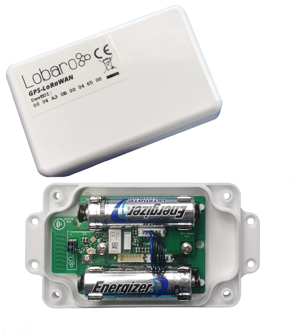
Variant without Power Addon
Order number: 8000014
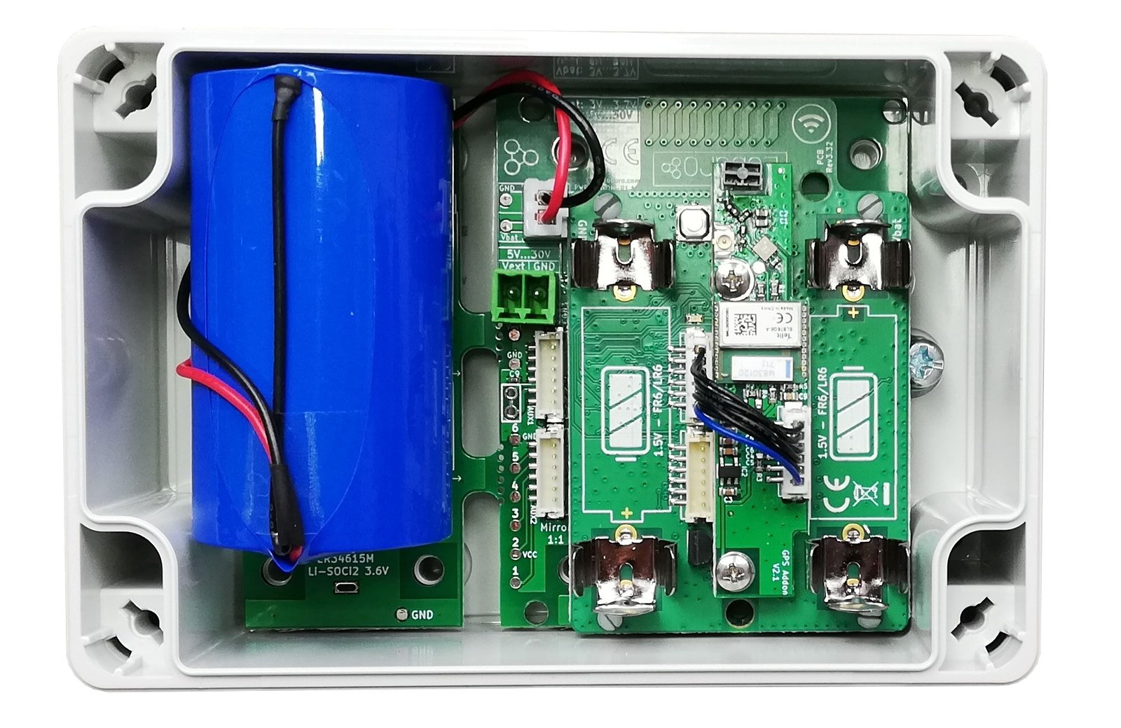
Variant with Power Addon
Order number: 8000082
Overview
The LoRaWAN GPS Tracker (GPS-LoRaWAN) is a battery-powered tracking device that uses the satellite-based positioning services GPS and GLONASS to determine its location and transmits the obtained coordinates via LoRaWAN radio technology. Intervals between measurements can be freely configured in order to adjust the device to individual needs.
An integrated motion sensor detects changes in the device's movement (if it is
picked up or transported in a vehicle). This allows the device to switch between
an Active Mode, in which frequent updates are uploaded during phases of
movement, and an Alive Mode that saves battery power by sending only few
updates. While not sending updates, the device enters a sleep mode that only uses
∼30 µA.
Please read the manual carefully before operating the device. Safe operation of the device is only possible if you follow the guides provided in this manual. Using the device differently than intended by Lobaro may cause damage to people, the environment, or the device.
Operating the GPS Tracker
Once batteries are inserted into the device, it will start working. The tracker will most likely need to be adjusted to your personal LoRaWAN configuration (see Configuration).
Batteries
The LoRaWAN GPS Tracker default power supply consists of two series-connected off-the-shelf 1.5 V 'AA' sized batteries. Be sure to get the polarity right — see the '+' symbol on the board. In general, only AA cells of the types Alkali-Manganese (1.5 V, LR6) and Lithium-Iron-Sulphide (1.5 V, FR6) are allowed to be inserted in the device. Lobaro recommends the use of FR6 batteries like the Energizer Ultimate Lithium over LR6 types because of the higher capacity and better discharge properties.
On request, we can supply custom product variants with special housings powered by even bigger batteries. For example, a 3.6 V C-sized mono cell typically has a capacity of 9 Ah, which leads to a 3× increased battery life compared to the standard AA cells. With D-sized cells of typically 19 Ah capacity, this value can be doubled once again (6×). Also available on request are options with permanent external power supply (230 V, 9–24 V, 5 V USB).
Installation
The device can be fixed on a flat surface using the lateral mounting holes of the case. Alternatively, we offer a mounting clip for a standard 35 mm DIN rail as an accessory.
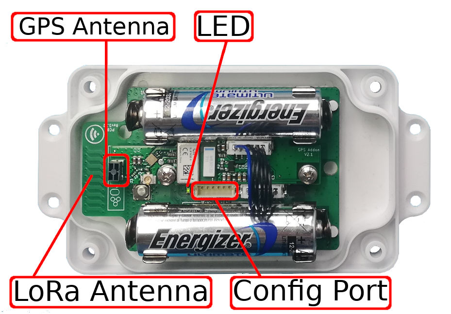
For optimal RF performance (e.g. LoRa range), any metal obstacles near the internal antenna should be avoided. In this case 'near' is defined as a keep-out distance of about 3–5 cm around the antenna. The internal helix antenna can be identified by the winding PCB traces near the white printed encircled 'connectivity' symbol. Mounting the device directly on top of a metal surface is not advisable, since it will degrade the possible RF range. Stone walls, wood, or plastic standoffs are perfectly fine. In case of challenging installation locations or unavoidable long distances to the next LoRaWAN gateway, Lobaro offers a custom product variant equipped with an 'SMA' connector to support an external antenna connection on request.
Work Cycle
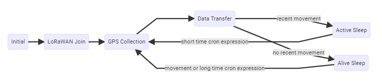
The GPS Tracker has a work cycle that adapts to detected motion of the device.
Initial Phase
This is the phase that is executed after the device is started or restarted. The LED flashes once and the configuration is evaluated. If successful, the LoRaWAN join phase is executed next.
LoRaWAN Join Phase
If the device is configured to use over-the-air activation (OTAA), the OTAA join is performed at this point. The device will repeatedly try to join its LoRaWAN network until the process is successful. It then enters the data collection phase. If the device is configured to use ABP instead of OTAA, this phase is left immediately and the data collection phase is entered.
GPS Collection Phase
During the GPS collection phase, the device will try to determine its coordinates (latitude, longitude, and height) using GPS. You can identify this phase by the onboard LED flashing on and off in one-second intervals. Once the position has been determined successfully (or the attempt timed out and failed because of bad GPS reception), the device enters the data transfer phase.
Data Transfer Phase
During the data transfer phase, the tracker uploads the GPS coordinates to the
LoRaWAN network. The message contains the information whether the measurement was
successful. Some status information about the device is included as well. After
data transfer, the GPS Tracker enters a sleep state to save power. Depending on
how much time passed since the last physical movement of the device, the tracker
enters different sleep phases. If the time since the last detected motion is less
than a timeout value (configurable, standard value is 65 minutes), the device
remains in Active Mode and enters only a short sleep phase (Active Sleep). If
no motion was detected for a time longer than the timeout, the device enters the
Alive Sleep phase, which typically has a much longer sleeping time, but in which
the device will also be activated through movement.
Active Sleep Phase
Even in Active Mode, the device spends most of its time in a deep sleep state to conserve energy. The frequency with which the tracker wakes up in Active Mode can be configured using a cron expression. Typical values for active sleep time are 5 or 15 minutes. When in Active Sleep phase, the device will not be triggered to gather more GPS positions through motion, but movement of the device will still be registered to keep the tracker in Active Mode.
Alive Sleep Phase
When no movement has been detected for a long amount of time (configurable), the device stops sending updates. In Alive Mode, only very few updates are sent to keep the network informed about the device's health. Typically one message is sent per day in this mode. When physical movement is detected by the internal motion sensor during this phase, the GPS Tracker immediately wakes up and switches to Active Mode.
Configuration
The Lobaro Maintenance Tool
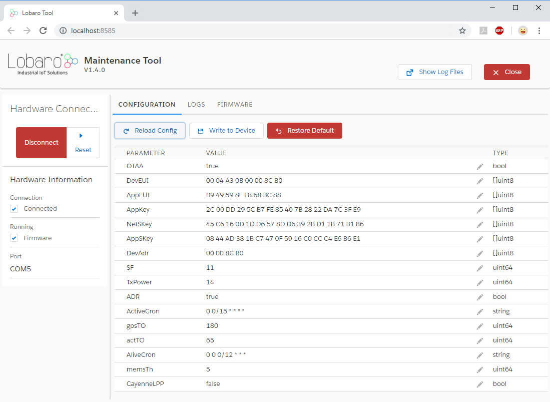
The initial device configuration can be done very comfortably from your PC via the serial configuration interface. Besides the needed Lobaro USB-to-UART adapter, the Lobaro Maintenance Tool needs to be installed. This tool is freely available for various operating systems including Windows, Linux, macOS, and Linux-ARM (e.g. Raspberry Pi) and works with all Lobaro sensors.
Technically, this software opens a web server on port 8585 that runs in a background console window. The actual user interface can be accessed normally using a standard web browser at address http://localhost:8585. Additionally to the device setup, the tool can also be used for firmware updates ('Firmware' tab), watching real-time device diagnostic output ('Logs' tab), and initiating device restarts.
Connecting the USB Config Adapter
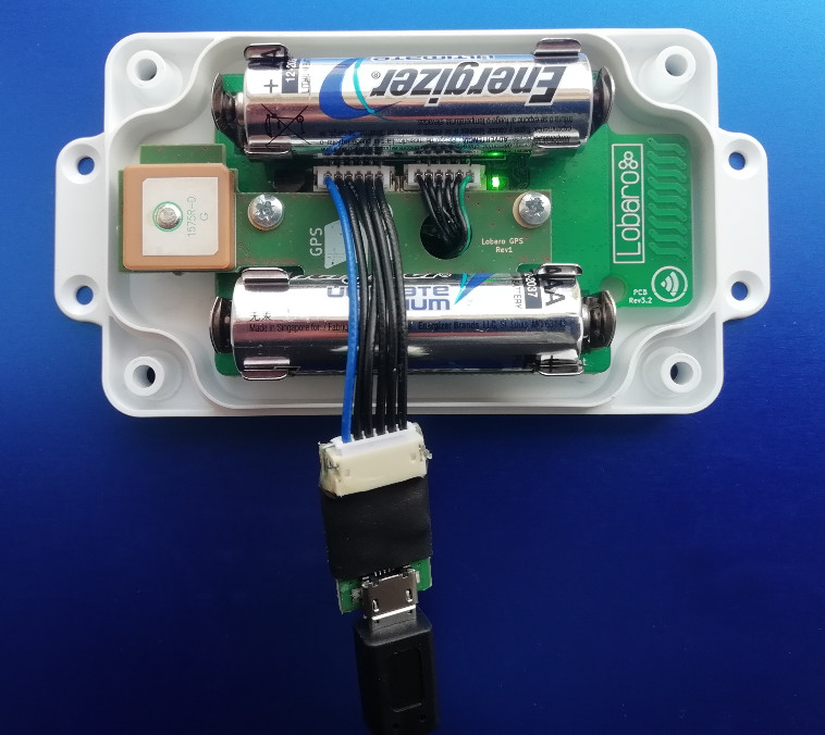
For configuration and firmware updates we provide a special serial-USB adapter (the Lobaro Config Adapter) that can be connected as shown in the picture below. The corresponding connector on the PCB is marked with the word 'Config'.
The USB adapter will add a virtual serial 'COM' port to your system. Your operating system needs the CP210x USB-to-UART bridge driver installed. While the config adapter is connected, the device will be powered from the USB port with a regulated voltage of 3.3 V. All configuration parameters will be kept non-volatile regardless of the power supply.
System Parameters
After being successfully connected to the hardware using the Lobaro Maintenance Tool, you can press 'Reload Config' in the 'Configuration' tab to read the current configuration from the device. For every parameter a default value is stored non-volatile inside the hardware, to which you can revert using the 'Restore default' button in case anything got misconfigured.
LoRaWAN
The connection to the LoRaWAN network is defined by multiple configuration parameters. These need to be set according to your LoRaWAN network and the way your device is supposed to be attached to it, or the device will not be able to send any data.
For a detailed introduction into how these values need to be configured, please refer to the LoRaWAN configuration chapter in our LoRaWAN background article.
| Name | Description | Type | Values |
|---|---|---|---|
OTAA | Activation: OTAA or ABP | bool | true = use OTAA, false = use ABP |
DevEUI | DevEUI used to identify the device | byte[8] | e.g. 0123456789abcdef |
JoinEUI | Used for OTAA (called AppEUI in v1.0) | byte[8] | e.g. 0123456789abcdef |
AppKey | Key used for OTAA (v1.0 and v1.1) | byte[16] | |
NwkKey | Key used for OTAA (v1.1 only) | byte[16] | |
SF | Initial / maximum spreading factor | int | 7-12 |
ADR | Use Adaptive Data Rate | bool | true = use ADR, false = don't |
OpMode | Operation mode | string | A = Class A, C = Class C |
TimeSync | Days after which to sync time | int | days, 0 = don't sync time |
RndDelay | Random delay before sending | int | max seconds |
RemoteConf | Not supported by this firmware | bool | false = deactivate |
LostReboot | Days without downlink before reboot | int | days, 0 = don't reboot |
GPS Configuration Parameters
The behaviour of the GPS Tracker and how it switches between its two operation modes ('Active' and 'Alive') can be adjusted to your needs.
| Name | Type | Description | Default value |
|---|---|---|---|
ActiveCron | string | Cron expression defining how often the device will take a measurement and send its position over LoRaWAN while in Active Mode. Should trigger much more frequently than the one for Alive Mode. | 0 0/15 * * * * |
AliveCron | string | Cron expression defining how often the device will wake up when in Alive Mode. Should be less frequent than in Active Mode. | 0 0 0/12 * * * |
gpsTO | int | Time in seconds to wait for GPS to get a fix before timing out. | 180 seconds |
actTO | int | Time in minutes without movement after which the tracker switches to Alive Mode. | 65 minutes |
memsTh | int | Threshold for the internal motion detector to register movement. Values range from 2 to 255; a higher value makes the device less sensitive. 2: environment (wind or steps) may trigger. 5: standard. 20: carefully picking it up will not trigger. 50: running triggers, walking won't. 100+: shaking activates. | 5 |
CayenneLPP | bool | Use alternative Cayenne LPP upload format instead of the Lobaro format. | false |
maxHDOP | int | Maximum acceptable Horizontal Dilution Of Precision, between 1 and 50, smaller is better. | 2 |
maxDataAfterFix | int | If the HDOP target cannot be matched, this value determines after how many data packets with a fix the position will be accepted. | 20 |
The schedules for data-collecting phases are defined using cron expressions. See our Introduction to CRON expressions for details.
LoRaWAN Data Upload Formats
After reading GPS coordinates (either successfully or unsuccessfully), the tracker uploads the data using LoRaWAN. As LoRaWAN can only transmit very short messages, the message formats contain only data bytes; no keys or data types are included. The meaning of a byte is determined by its position within a message.
Lobaro Upload Format (since Firmware Version 5)
Only a single message format is used by the GPS Tracker; it has a fixed length of 17 bytes. This format uses the decimal degrees notation for the location, e.g. 53.4724° north and 9.9334° east. Positive (+) values indicate north latitudes and east longitudes, negative (−) values indicate south latitudes and west longitudes. Both location values are transmitted as signed integers in big endian format and multiplied by 100000, so after receiving, the location data must be divided by this factor. Multi-byte integers are transmitted as big endian.
| Name | Bytes | Type | Description | Example / range |
|---|---|---|---|---|
| temp | 0-1 | int16 | Temperature inside the device in 1/10 °C | 246 = 24.6 °C |
| v_bat | 2-3 | uint16 | Current battery voltage in mV | 3547 = 3.547 V |
| latitude deg | 4-7 | int32 | Degrees of the latitude × 100000 | -9000000 to 9000000 |
| longitude deg | 8-11 | int32 | Degrees of the longitude × 100000 | -18000000 to 18000000 |
| altitude | 12-14 | int24 | Altitude of the device in centimeters | -8388607 to 8388606 |
| flags | 15 | uint8 | Status flag, refer to table below | 00 = invalid, alive; 01 = valid, alive; 10 = invalid, active; 11 = valid, active |
| sat | 16 | uint8 | GPS satellites found / in view | 7 |
Status Flag
| Bit | Function | Not set | Set |
|---|---|---|---|
| 1 | Validity of last measurement | invalid | valid |
| 2 | Current operation mode | alive | active |
| 3-8 | reserved for future use |
If during some configurable period of time (see the gpsTO parameter) no GPS
location can be found, the last known valid GPS location will be transmitted but
with the valid flag set to false.
myDevices Cayenne Format
As an alternative to the Lobaro data format, the tracker can be configured to send
Cayenne LPP compatible LoRaWAN uploads. myDevices Cayenne
allows you to quickly visualize the data transmitted via LoRaWAN. To use the
alternative upload format, the configuration parameter CayenneLPP must be set to
true. The advantage of using the Cayenne format is a quick device evaluation
without programming a custom backend and/or frontend software. Disadvantages are
bigger LoRaWAN message sizes due to the additional schema meta-information overhead
the format needs.
The Lobaro GPS Tracker maps its data to Cayenne channels as follows:
| Description | Cayenne channel | Cayenne type |
|---|---|---|
| Internal temperature | 0 | Temperature |
| Battery voltage | 1 | AnalogOutput |
| GPS data | 2 | GPS |
| Satellites found | 3 | Digital Output |
Legacy Upload Format (up to Firmware Version 4)
This format is not supported any more since firmware version V5.0.0. Please consider updating your device firmware using the Lobaro Maintenance Tool.
Only a single message format is used by the GPS Tracker; it has a fixed length of 15 bytes. This format uses the degrees-with-decimal-minutes notation for the location. Multi-byte integers are transmitted as big endian.
Parser
The Things Network
Reference decoder for firmware versions 4.x, 5.x and 6.x, usable as is in The Things Network.
function signed(val, bits) {
    if ((val & 1 << (bits-1)) > 0) { // value is negative (16bit 2's complement)
        var mask = Math.pow(2, bits) - 1;
        val = (~val & mask) + 1; // invert all bits & add 1 => now positive value
        val = val * -1;
    }
    return val;
}

function int16_BE(bytes, idx) {
    bytes = bytes.slice(idx || 0);
    return signed(bytes[0] << 8 | bytes[1] << 0, 16);
}

function int24_BE(bytes, idx) {
    bytes = bytes.slice(idx || 0);
    return signed(bytes[0] << 16 | bytes[1] << 8 | bytes[2] << 0, 24);
}

function int32_BE(bytes, idx) {
    bytes = bytes.slice(idx || 0);
    return signed(bytes[0] << 24 | bytes[1] << 16 | bytes[2] << 8 | bytes[3] << 0, 32);
}

function DecoderPort2(bytes) {
    // Format for firmware 5.0.x
    // Decode an uplink message from a buffer
    // (array) of bytes to an object of fields.

    var Temp = int16_BE(bytes, 0) / 10;
    var VBat = int16_BE(bytes, 2) / 1000;
    var Lat = int32_BE(bytes, 4) / 100000;
    var Lon = int32_BE(bytes, 8) / 100000;
    var Alt = int24_BE(bytes, 12) / 100;
    var Valid = bytes[15] & 0x01;
    var Active = bytes[15] & 0x02;
    var SatCnt = bytes[16];

    return {
        Temp: Temp || 0,
        VBat: VBat || 0,
        Lat: Lat || 0,
        Lon: Lon || 0,
        Alt: Alt || 0,
        Valid: Valid,
        Active: Active,
        SatCnt: SatCnt
    };
}

function DecoderPort1(bytes) {
    // legacy format, firmware 4.x
    // Decode an uplink message from a buffer
    // (array) of bytes to an object of fields.

    var button_number = bytes[0];
    var Temp10tel = (bytes[1] << 8) | (bytes[2] << 0);
    var VBat1000tel = (bytes[3] << 8) | (bytes[4] << 0);
    var lat_deg = bytes[5];
    var lat_min = bytes[6];
    var lat_10000min = (bytes[7] << 8) | (bytes[8] << 0);
    var long_deg = bytes[9];
    var long_min = bytes[10];
    var long_10000min = (bytes[11] << 8) | (bytes[12] << 0);
    var gpsValid = (bytes[13] !== 0);  // Missing byte = true

    return {
        button_number:button_number || 0,
        Temp10tel: Temp10tel || 0,
        VBat1000tel: VBat1000tel || 0,
        lat_deg: lat_deg || 0,
        lat_min: lat_min || 0,
        lat_10000min: lat_10000min || 0,
        long_deg: long_deg || 0,
        long_min: long_min || 0,
        long_10000min: long_10000min || 0,
        gps_valid: gpsValid || false
    };
}

function Decoder(bytes, port) {
    switch (port) {
        case 1:
            return DecoderPort1(bytes);
        case 2:
            return DecoderPort2(bytes);
        default:
            return {"error":"Unsupported port","port":port};
    }
}

// Wrapper for Lobaro Platform
function Parse(input) {
    // Decode an incoming message to an object of fields.
    var b = bytes(atob(input.data));
    var decoded = Decoder(b, input.fPort);

    return decoded;
}

// Wrapper for Loraserver / ChirpStack
function Decode(fPort, bytes) {
    return Decoder(bytes, fPort);
}
Firmware
Available firmware versions and release notes are listed on the Firmware & Changelog page.
Technical Characteristics
Product
| Property | Value |
|---|---|
| Type name | GPS-LoRaWAN |
| Description | LoRaWAN GPS Tracker |
RF transceiver
| Property | Value |
|---|---|
| Chipset | Semtech SX1272 |
| Frequency range | 863 to 870 MHz |
| TX power | ≤ 14 dBm |
| Typical RF range | ≤ 2 km |
| Ideal RF range | ≤ 10 km (free line of sight) |
LoRa communication
| Property | Value |
|---|---|
| LoRaWAN protocol | LoRaWAN 1.0.1, Class A, EU868 |
| Activation method | Over-the-air activation (OTAA), Activation by personalization (ABP) |
| Encryption | AES128 |
Power
| Property | Value |
|---|---|
| Power supply | 2× AA-sized battery, 1.5 V, LR6/FR6 |
| Supply voltage | U |
| Capacity | ∼ 30000 LoRaWAN messages @ SF11 |
Current consumption @ 3 V
| Property | Value |
|---|---|
| Normal | ≤ 3 mA |
| Wireless M-Bus RX | ≤ 14 mA |
| LoRa RX | ≤ 14 mA |
| LoRa TX | ≤ 80 mA |
| Sleep with GPS standby and MEMS running | ≤ 20 µA |
Mechanical dimensions
| Property | Value |
|---|---|
| Size | 114.3 mm × 59.3 mm × 26.8 mm |
| Housing material | ABS plastic |
Environmental requirements
| Property | Value |
|---|---|
| Operating temperature range | -20 °C to +55 °C |
| Max. installation height | 2 m |
PDF Documentation
- User Manual (en) (PDF)
- Product Dimensions (PDF)
- CE Declaration of Conformity (PDF)