Gateway V4 + DIN-Rail
Wireless M-Bus Gateway V4 with the DIN-Rail add-on: a DIN-rail variant for combined wired M-Bus, Modbus and Ethernet installations.
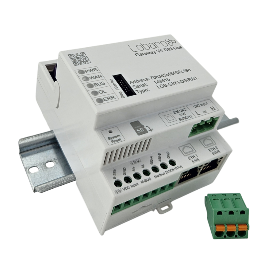
Description
Gateway for remote reading of wireless M-Bus, wired M-Bus, Modbus (RTU / ASCII) and Modbus TCP values via Ethernet, NB-IoT, LTE-M or LoRaWAN. Housed in a DIN-rail enclosure for 35 mm rails (EN 60715), 4 modules (72 mm) wide, with two 10/100 Mbit Ethernet ports. For indoor installation only, e.g. in a distribution or meter cabinet.
Features
All Gateway V4 Series platform features plus:
- Wired M-Bus master with primary and secondary addressing, automatic meter scan and overload protection since v0.16.0
- Modbus master (read only):
- Modbus ASCII / RTU via RS-485, several UART configurations in one configuration
- Modbus TCP over Ethernet, selectable per device via ETH1 (LAN) or ETH2 (WAN)
- RS-485 and Modbus TCP can be mixed in one
modbusCmdConf
- 2× 10/100 Mbit Ethernet (LAN + WAN), each with DHCP or static IP (optional DNS server)
- Uplink via Ethernet with LTE fallback (default), Ethernet only, LTE or LoRaWAN
- Live Mode via Ethernet, LTE and LoRaWAN
- Mounts on a standard 35 mm DIN rail (EN 60715), 4 modules (72 mm) wide
- Power supply: 9–36 V DC (terminal block) and/or 230 V AC (SMGW terminal plug), DC input has priority
Product Components
- Firmware
- app-nrf91-origin (build
hw4.dinrail) · Firmware updates - Housing
- DIN-rail enclosure for 35 mm rails (EN 60715), 4 modules (72 mm) wide
- Power supply
- 9–36 V DC (terminal block) and/or 230 V AC (SMGW terminal plug), DC input has priority · no battery
- Optional accessories
- USB Config Adapter
Connections
The DIN-Rail gateway provides two Ethernet ports (RJ45), a 7-pole screw terminal block (5.08 mm pitch), the Diag. / Service interface and one FAKRA antenna connector.
Ethernet
| Port | Label | Usage |
|---|---|---|
| ETH1 | LAN | Modbus TCP (default port for Modbus TCP) |
| ETH2 | WAN | Data upload (Ethernet uplink), Modbus TCP (selectable per device) |
Both ports are 10/100 Mbit Ethernet.
Terminal Block
Terminals from left to right:
| Terminal | Signal | Function |
|---|---|---|
| 1 | 9-36V | Supply voltage, 9–36 V DC |
| 2 | GND | Supply ground |
| 3 | M+ | Wired M-Bus master since v0.16.0 |
| 4 | M- | Wired M-Bus master since v0.16.0 |
| 5 | 485-A | RS-485 A |
| 6 | 485-B | RS-485 B |
| 7 | GND | RS-485 signal ground |
- M-Bus: wired M-Bus master since v0.16.0. Configure it with the M-Bus Add-On parameters.
- RS-485: half-duplex Modbus RTU / ASCII master. There is no bus termination inside the device. Add a 120 Ω termination externally if your bus requires it.
- Power: The gateway has two power inputs: 9–36 V DC via the terminal block and 230 V AC via the SMGW terminal plug (VAC Input, L / N). Connect either one, or both. If DC is present, the gateway runs on DC; otherwise it switches over to the 230 V AC input automatically. The 230 V AC input has an internal slow-blow fuse (T 2 A, 250 V AC).
Diag. / Service
The Diag. / Service connector next to the LEDs is the configuration interface of the gateway. Connect the USB Config Adapter here for local configuration, diagnostics and firmware updates.
Antenna
The gateway has one FAKRA Code D connector for a combined LTE and wM-Bus / LoRaWAN antenna. Any FAKRA Code D antenna that meets the antenna requirements can be used, e.g. the FAKRA Indoor Antenna (Panorama IN2214).
Antenna Requirements
The antenna must meet the following requirements:
| Requirement | Value |
|---|---|
| Connector | FAKRA Code D (bordeaux violet) jack, female centre contact |
| Connector size | Max. 13.5 mm across the coding key, max. 15.5 mm perpendicular to the key, max. 22.0 mm from mating face to rear |
| Frequency range | Must cover 791–960 MHz (LTE B20, B8, wM-Bus / LoRaWAN 868 MHz) and 1710–1880 MHz (LTE B3) |
| VSWR | < 2:1 in the bands above |
| Gain | ≥ 2 dBi peak, omnidirectional |
| Impedance | 50 Ω |
- Connector size: The antenna connector of the gateway sits in a recess in the housing. Larger FAKRA connectors do not fit. A right-angle connector with the cable exit in line with the coding key is recommended (cable exit centre max. 14.0 mm from the mating face).
- Cable: Every metre of thin coaxial cable costs signal. Keep the cable as short as the installation allows. In control cabinets a thin, flexible cable is easier to route through cable entries and door seals.
- One antenna for all radios: The single FAKRA connector serves LTE as well as wM-Bus / LoRaWAN. A single-band antenna (e.g. LTE only) degrades the other radio.
SD Card Slot
The micro SD card slot is currently not used by the firmware.
Reset Button
Unlike the other Gateway V4 variants, the reset button of the DIN-Rail gateway is recessed in the housing. Press it with a paper clip or a similar thin tool.
Product Identification
- Name: Wireless M-Bus Gateway V4 DIN-Rail
- Type: LOB-GW4-DINRAIL
- Order code:
1201406 - Device type on the Lobaro Platform: Gateway V4 Dinrail
Accessories
| Accessory | Notes |
|---|---|
| USB Config Adapter | For local configuration, diagnostics, and firmware updates |
| FAKRA Indoor Antenna (Panorama IN2214) | Multiband wall-mount antenna with 3 m cable for LTE and wM-Bus / LoRaWAN, order code 1201450 |
LEDs
The DIN-Rail gateway has five LEDs on the front, labelled from top to bottom:
| LED | Meaning |
|---|---|
| PWR | Power |
| WAN | Uplink connection (Ethernet, LTE or LoRaWAN) |
| BUS | Bus communication (M-Bus, Modbus) |
| OL | M-Bus overload |
| ERR | Error |
The LED signalling does not work correctly with the current firmware yet. It will be completed in upcoming firmware releases. The standard V4 LED signal patterns do not apply to this device.
Configuration
The device is shipped with default configuration parameters. Local changes can be made via the config port using the USB Config Adapter and the Lobaro Config Tool.
For step-by-step instructions, see the Configuration Methods guides:
- 🔌 Local Config via USB — connect directly to the device
- 📡 Remote Config via CoAP — over NB-IoT / LTE-M via Lobaro Platform
- 📻 Remote Config via LoRaWAN — via LoRaWAN downlink
- 🔗 Remote Config via MQTT — for 3rd party MQTT backends
Custom factory configuration is available on request — devices can be pre-configured at production for your specific deployment. Contact sales@lobaro.de when ordering.
Configuration Parameters
All meter interfaces (Modbus, wired M-Bus, wireless M-Bus) are disabled in the default configuration since v0.16.0. The gateway reads and uploads no meter data until you configure at least one of them, see the DIN-Rail Add-On parameters.
This product runs the app-nrf91-origin firmware:
- Common firmware parameters
- DIN-Rail Add-On parameters: Ethernet, Modbus RTU / ASCII and Modbus TCP (see also Modbus Config Generator: builds the Modbus requests for
modbusCmdConf) - M-Bus Add-On parameters: wired M-Bus since v0.16.0
Firmware Updates
The latest firmware can be found here:
- Download latest firmware
-
For further information on how to update the device, refer to: Firmware Update.
A remote firmware update over LoRaWAN is currently not possible.
Use the firmware variant hw4.dinrail since v0.15.0 (up to firmware 0.14.x: hw4.edge), e.g. app-nrf91-origin+0.15.0+hw4.dinrail~boot.hex for a local update via USB or app-nrf91-origin+0.15.0+hw4.dinrail.hex for a remote update. All Gateway V4 variants run the app-nrf91-origin firmware.
LoRaWAN Uplink Formats
- LoRaWAN Protocol: Status Packet (Port 1) and wM-Bus uplink formats
- DIN-Rail Add-on LoRaWAN Uplinks
- M-Bus Add-on LoRaWAN Uplinks: wired M-Bus
Cellular and Ethernet Uplink
With MQTT over Ethernet, time synchronization is currently not supported. With CoAP to the Lobaro Platform, the device gets the time from the platform. With WAN set to ethernet+lte, the time is synchronized as soon as LTE is used.
Uplink Parser
A production-ready parser for the uplinks of this device is implemented within the Lobaro Platform. It covers the wireless M-Bus telegrams (including split telegram reassembly where applicable, AES-128 decryption for encrypted telegrams, and OMS-compliant data interpretation) as well as the add-on data of the respective variant, for example Modbus responses or sensor values.
Customers using the Lobaro Platform can utilize this parser directly as part of the platform processing pipeline.
If you are operating a Lobaro Gateway without using the Lobaro Platform, we can provide restricted platform access upon request. This allows you to inspect the parser behavior and use it as a technical reference for your own backend implementation.
Please contact our support team if you require access or further integration details.